00196693-03_UM_SX4DX4_SR706_EN.pdf - 第80页
2 Operational safety User Manual SIPLACE SX4/DX4 2.8 Residual voltages and discharge times in the mach ine From software version SC.706.xx Version 06/2012 EN 80 2.8.1 Residual volt ages and discharge tim es after switchi…
User Manual SIPLACE SX4/DX4 2 Operational safety
From software version SC.706.xx Version 06/2012 EN 2.8 Residual voltages and discharge times in the machine
79
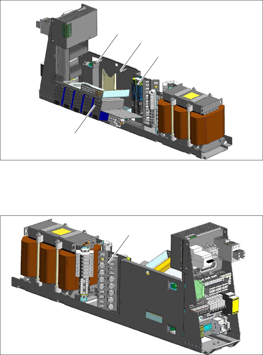
Fig. 2.8 - 2 Measuring point X200 on the power supply unit
(1) Distributor terminal block X200
In order to access the X200 terminal strip, both fastening screws (2) on the service flap (3) must
be loosened and the flap folded down.
2
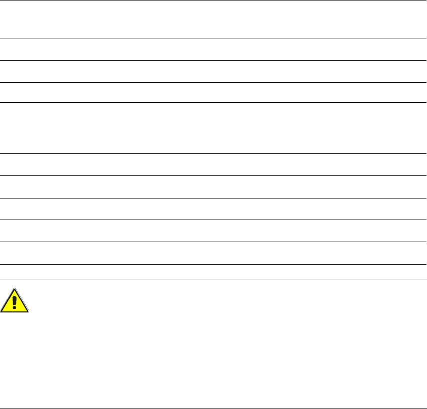
Fig. 2.8 - 3 Interface-machine cable tree on the power supply unit
(1) Interface-machine cable tree
(1)
(2)
(2)
(3)
(1)

2 Operational safety User Manual SIPLACE SX4/DX4
2.8 Residual voltages and discharge times in the machine From software version SC.706.xx Version 06/2012 EN
80
2.8.1 Residual voltages and discharge times after switching off the main switch
2
Measuring point on the X200
distributor terminal block
Voltage in
normal mode
Residual voltage if
main switch OFF or
power failure
Discharge
times
X200 - 1.a 260 V- < 10 VDC < 2s
X200 - 4.a 150 V- < 10 VDC < 2s
X200 - 17.a 42 V- (permanent) < 10 VDC < 2s
X200 - 17.a 42 V- (switched) < 10 VDC < 2s
X200-13.a 24 V- < 10 VDC < 2s
Interface-machine cable tree Voltage in
normal mode
Residual voltage if
main switch OFF or
power failure
Discharge
times
X21 - 1 260 V- < 10 VDC < 2s
X31 - 1 150 V- < 10 VDC < 2s
A8 ( positive connection) 42 V- (permanent) < 10 VDC < 2s
X18 - 7 42 V- (switched) < 10 VDC < 2s
X17 - 1 24 V- < 10 VDC < 2s
User Manual SIPLACE SX4/DX4 2 Operational safety
From software version SC.706.xx Version 06/2012 EN 2.8 Residual voltages and discharge times in the machine
81
2.8.2 Residual voltages and discharge times after pressing the EMERGENCY
STOP button
2
2
CAUTION 2
To avoid losing data, assess the following criteria before switching off your machine (apart from in
emergencies):
– Has the machine finished transmitting machine, setup and panel data?
– Has the machine finished processing the PCB?
– Has the machine completed the run-up phase?
Measuring point on the X200
distributor terminal block
Voltage in
normal mode
Residual voltage after
EMERGENCY STOP
Discharge
times
X200 - 4.a 150 V- < 10 VDC < 2s
X200-13.a 24 V- < 10 VDC < 2s
Interface-machine cable tree Voltage in
normal mode
Residual voltage if
main switch OFF or
power failure
Discharge
times
X21 - 1 260 V- < 10 VDC < 2s
X31 - 1 150 V- < 10 VDC < 2s
A8 ( positive connection) 42 V- (permanent) < 10 VDC < 2s
X18 - 7 42 V- (switched) < 10 VDC < 2s
X17 - 1 24 V- < 10 VDC < 2s