00196693-03_UM_SX4DX4_SR706_EN.pdf - 第205页
User Manual SIPLACE SX4/DX4 4 Setting up and commissioning From software version SC.706.xx V ersion 06/2012 EN 4.2 Infrastructure at the installation location 205 4 T erminal pa n e l Vo l t a g e 1U1 415 VAC 1V1 415 VAC…
4 Setting up and commissioning User Manual SIPLACE SX4/DX4
4.2 Infrastructure at the installation location From software version SC.706.xx Version 06/2012 EN
204
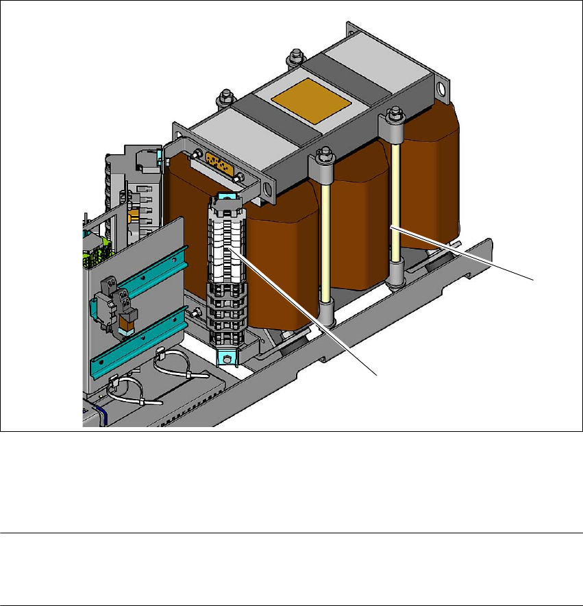
4.2.3.6 Checking connections to the primary side of the three-phase transformer T1
The primary side of the three-phase transformer must be configured for the relevant supply volt-
age.
Check the terminal strip (1) to make sure that the primary end of the three-phase transformer
is correctly connected for the relevant supply voltage.
4
Fig. 4.2 - 6 Terminal panel for the primary side of the three-phase transformer T1
(1) Terminal panel with primary connections for the three-phase transformer T1
(2) Three-phase transformer
PLEASE NOTE 4
The supply networks for North Japan (3 x 200 V~) and for the USA (
3 x 208 V~) are connected to the terminals for 3 x 204 V~.
The following overview shows the connection options for the primary voltages of the three-phase
transformer.
(1)
(2)

User Manual SIPLACE SX4/DX4 4 Setting up and commissioning
From software version SC.706.xx Version 06/2012 EN 4.2 Infrastructure at the installation location
205
4
Terminal
panel
Voltage
1U1 415 VAC
1V1 415 VAC
1W1 415 VAC
3U3 400 VAC
3V3 400 VAC
3W3 400 VAC
4U4 380 VAC
4V4 380 VAC
4W4 380 VAC
5U5 230 VAC
5V5 230 VAC
5W5 230 VAC
6U6 220 VAC
6V6 220 VAC
6W6 220 VAC
7U7 204 VAC
7V7 204 VAC
7W7 204 VAC
4 Setting up and commissioning User Manual SIPLACE SX4/DX4
4.2 Infrastructure at the installation location From software version SC.706.xx Version 06/2012 EN
206
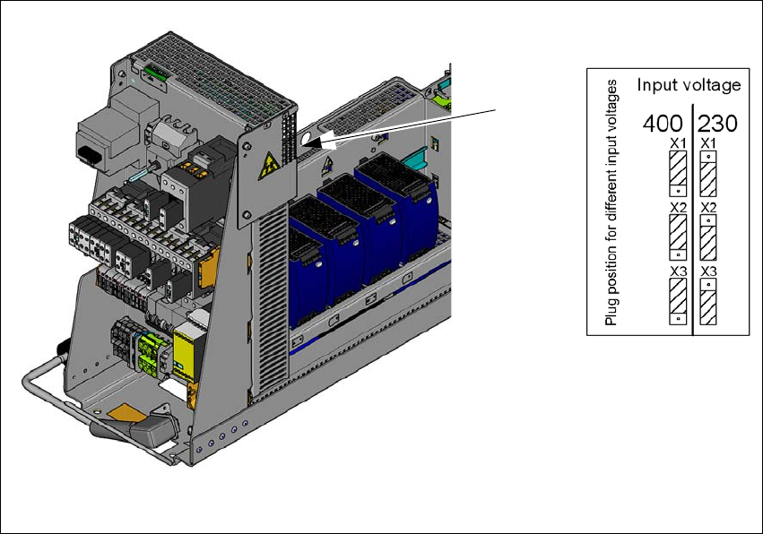
4.2.3.7 Checking the inrush current limitation jumpers
The inrush current limiter of the transformer (A2) is connected in the same manner for all supply
voltages. The connectors must all be plugged into the position for input voltage 230V.
4
Fig. 4.2 - 7 Position of the board and connectors for the inrush current limitation
(1) Position of the inrush current limitation (A2)
(2) Configuration schema
Check the connector assignment for the inrush current limiter of the transformer. The connec-
tors for all mains voltages need to be plugged into the Input Voltage 230V point.
(1)
(2)