00196693-03_UM_SX4DX4_SR706_EN.pdf - 第217页
User Manual SIPLACE SX4/DX4 4 Setting up and commissioning From software version SC.706.xx V ersion 06/2012 EN 4.3 Setting up the machine 217 Screw the thread of the middle ma chine foot into the hole provided on the u…
4 Setting up and commissioning User Manual SIPLACE SX4/DX4
4.3 Setting up the machine From software version SC.706.xx Version 06/2012 EN
216
Screw the thread of the middle machine foot into the hole provided on the underside of the
spacer.
Align the two spacers on the machine underside as follows:
– The spacer opening on the pneumatic unit side points in the direction of board conveyor
travel (see item 4 in fig. 4.3 - 4
, page 214).
– The spacer opening on the power supply side points in the opposite direction to that of
conveyor travel (see item 3 in fig. 4.3 - 4
, page 214).
Fasten each of the two spacers with four hexagon socket-head screws M12x80 (see item 4
in fig. 4.3 - 5
). Use the screwdriver bit of size 10 mm.
Setting a board conveyor height of 930 and 950 mm 4
You also need the spacer for the board conveyor heights 930 mm and 950 mm.
Make sure that the 122.5 mm side of the spacer is vertically aligned and the hole for the mid-
dle machine foot indicates downwards.
4
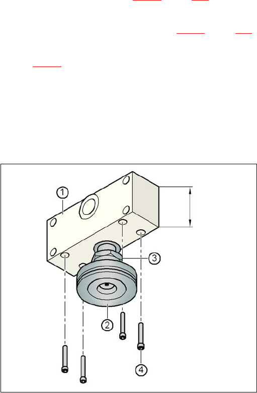
Fig. 4.3 - 6 Aligning the spacer for a conveyor heights of 930 and 950 mm
4
(1) Spacer height of 122.5 mm
(2) Machine foot
(3) Lock nut M24
(4) Hexagon socket head screw M12x80, 4x
122.5 mm
User Manual SIPLACE SX4/DX4 4 Setting up and commissioning
From software version SC.706.xx Version 06/2012 EN 4.3 Setting up the machine
217
Screw the thread of the middle machine foot into the hole provided on the underside of the
spacer.
Align both spacers as follows:
– The spacer opening on the pneumatic unit side points in the direction of board conveyor
travel (see item 4 in fig. 4.3 - 4
, page 214).
– The spacer opening on the power supply side points in the opposite direction to that of
conveyor travel (see item 3 in fig. 4.3 - 4
, page 214).
Fasten each of the two spacers with four hexagon socket-head screws M12x80 (see item 4
in fig. 4.3 - 6
). Use the screwdriver bit of size 10 mm.
4.3.6.2 Presetting the height of the outer machine feet
4
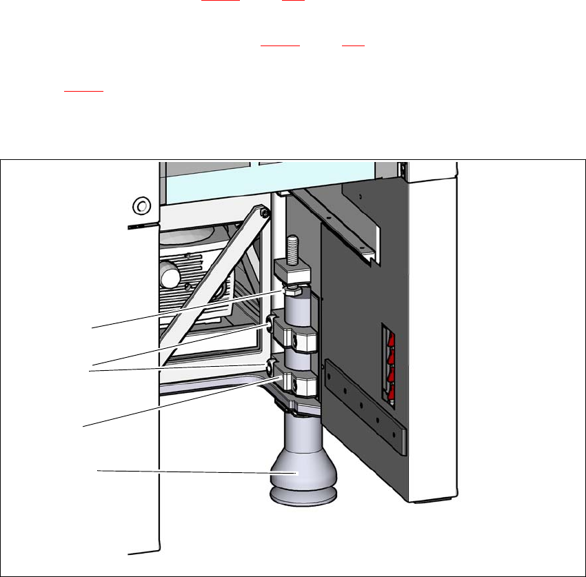
Fig. 4.3 - 7 Presetting the height of the outer machine feet
(1) Setting screw M24x2x120 for height adjustment
(2) Outer machine foot
(3) Clamping piece
(4) Hexagon socket-head screw M24x90
(4)
(2)
(1)
(3)

4 Setting up and commissioning User Manual SIPLACE SX4/DX4
4.3 Setting up the machine From software version SC.706.xx Version 06/2012 EN
218
Carefully loosen both hexagon socket-head screws M24x90 (item 2 in fig. 4.3 - 7, page 217)
with the screwdriver bit (size 19 mm) and let the outer machine foot (item 1 in fig. 4.3 - 7
, page
217
) slowly slide down as far as the end stop.
Insert the correct machine foot for the required PCB conveyor height.
There are two versions of the outer machine feet: 4
– Outer machine feet for the PCB conveyor height 830 mm, length 369 mm,
Item no. 03041008-01 (item 1 in fig. 4.3 - 4
, page 214 )
– Outer machine feet for the PCB conveyor heights 900,930 and 950 mm, length
439 mm, Item no. 03000890-02 (item 2 in fig. 4.3 - 4
, page 214 )
Perform this presetting for each of the outer machine feet.
The distance between the machine foot underside and the lower edge of the machine frame
should be as follows:
Adjust the setting screw M24x2x120 (item 3 in fig. 4.3 - 7, page 217) with the fork wrench SW
36, so that you achieve the distance values for the relevant conveyor height, as specified in
the table above.
Now use the fork-lift to carefully lower the machine until the machine feet touch the floor
evenly. There should always be a second person present to ensure that the machine remains
stable while it is being lowered. You may need to loosen the outer machine feet clamp slightly.
Continue to carefully lower the machine, until the outer machine feet touch the height adjust-
ment setting screws M24x2x120 (item 3 in fig. 4.3 - 7
, page 217).
Make sure that the middle machine feet (see item 2 in fig. 4.3 - 4, page 214) do not yet touch
the ground. If necessary, screw the middle machine feet back into the machine or spacer a
little.
PLEASE NOTE 4
For a description of how to perform final adjustment on the machine, refer to the section
4.3.8.2, page 226.
PCB conveyor height Distance of machine foot underside to lower edge of
machine frame
900 mm 190 mm
930 mm 220 mm
950 mm 240 mm