00196693-03_UM_SX4DX4_SR706_EN.pdf - 第72页
2 Operational safety User Manual SIPLACE SX4/DX4 2.7 Safety equipment From software version SC.706.xx Version 06/2012 EN 72 Protective contactor combination K6 ( item 1 in fig. 2.7 - 6 , page 71 ) 2 The prot ective conta…
User Manual SIPLACE SX4/DX4 2 Operational safety
From software version SC.706.xx Version 06/2012 EN 2.7 Safety equipment
71
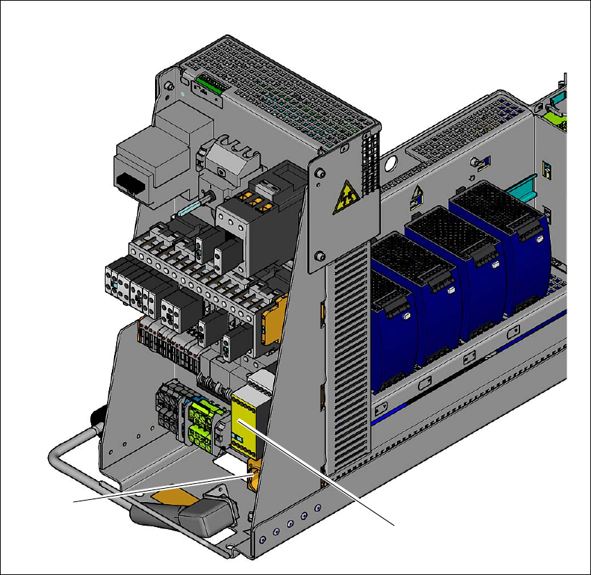
2.7.3 Position of protective contactor combination and service socket
2
Fig. 2.7 - 6 Position of protective contactor combination and service socket
2
(1) Protective contactor combination
(2) Service socket
(2)
(1)
2 Operational safety User Manual SIPLACE SX4/DX4
2.7 Safety equipment From software version SC.706.xx Version 06/2012 EN
72
Protective contactor combination K6 ( item 1 in fig. 2.7 - 6, page 71) 2
The protective contactor combination is contained in the power supply unit. It is used to monitor
the EMERGENCY STOP circuits and safety equipment.
There are three conditions that must be fulfilled in order to activate the protective contactor com-
bination:
– The "software release" or "Control ON" signal must be issued.
– The EMERGENCY STOP loop must be closed.
– The start button must have been pressed.
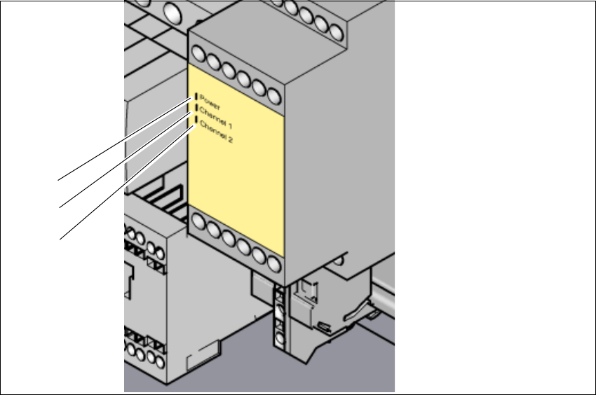
The front side of the protective contactor combination has three green LEDs for the operating dis-
play (see fig. 2.7 - 7
, page 73 )
– The "Power" LED indicates that voltage is present.
– The "Channel 1" and "Channel 2" LEDs shine if the start button has been pressed, the EMER-
GENCY STOP circuit is closed and the signaling circuit has not indicated any error states.
Service socket ( item 2 in fig. 2.7 - 6, page 71) 2
The service socket is contained in the power supply unit and is protected by the cover. It can only
be used if the machine is connected to the main power supply via a 5-wire connection (L1, L2, L3,
N, and PE). If a 4-wire connection is used, e.g. without N, the socket cannot be used.
WARNING 2
Always follow the safety instructions concerning potentially lethal voltages - even when the
machine is switched off. (See section 2.1.3 from page 32 and section 2.7.2.3 from page 69 .
User Manual SIPLACE SX4/DX4 2 Operational safety
From software version SC.706.xx Version 06/2012 EN 2.7 Safety equipment
73
2.7.4 EMERGENCY STOP loops and signaling circuit
2.7.4.1 Structure of the EMERGENCY STOP loops
The following contacts are connected in series and form the EMERGENCY STOP loop:
– Make contact elements for the four protective cover switches
– Normally open (NO) contacts for the two EMERGENCY STOP buttons
– Make contact elements for the four component trolleys/DX changeover tables
– Channels for the protective contactor combination SSK K6
In addition to analyzing the EMERGENCY STOP loop with the SSK K6, the software also checks
the signaling contacts of the monitored switches. If all contacts are closed (make contact), the soft-
ware sends a digital CAN bus output signal from the I/O control unit to the SSK K6.
2
Fig. 2.7 - 7 Signal LED on the protective contactor combination
(1) Mains / Power
(2) Kanal 1 / Channel 1
(3) Kanal 2 / Channel 2
(1)
(2)
(3)