00196693-03_UM_SX4DX4_SR706_EN.pdf - 第315页
User Manual SIPLACE SX4/DX4 6 Station extensions From software version SC.706.xx Version 06/2012 EN 6.2 DX changeover tables on the SIPLACE DX4 315 PLEASE NOTE: Feeder modules can be plac ed on the uneven track numbers. …
6 Station extensions User Manual SIPLACE SX4/DX4
6.2 DX changeover tables on the SIPLACE DX4 From software version SC.706.xx Version 06/2012 EN
314
6.2 DX changeover tables on the SIPLACE DX4
Item no. 03089820-xx DX changeover table SIPLACE DX4 with 40/2 tracks
Item no. 03089961-xx DX changeover table docking unit for 40/2 tracks
Just like the fixed DX tables, the DX changeover tables are optimized for the use of 2x8 mm SI-
PLACE tape feeder modules when using 8 mm tapes. By using 20 of these feeder modules, you
can achieve a full setup capacity of 40 8mm tracks. The design and function of the DX changeover
tables is basically identical to that of the component changeover tables for the SIPLACE SX4 ma-
chines. See “SIPLACE X series changeover table” on page 181.
6
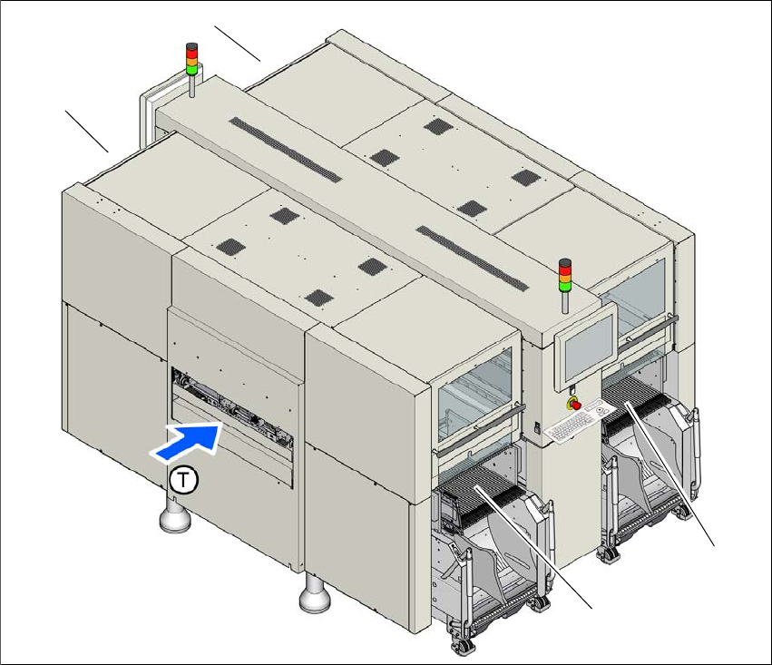
Fig. 6.2 - 1 DX changeover table locations, SIPLACE DX4
(1) Location 1
(2) Location 2
(3) Location 3
(4) Location 4
(T) Direction of PCB transport
(1)
(4)
(2)
(3)
User Manual SIPLACE SX4/DX4 6 Station extensions
From software version SC.706.xx Version 06/2012 EN 6.2 DX changeover tables on the SIPLACE DX4
315
PLEASE NOTE:
Feeder modules can be placed on the uneven track numbers. Only these tracks are fitted with an
energy and data interface on the machine, so that the full capacity of 40 8mm tracks can be
achieved with 20 2x8mm X feeder modules. 6
CAUTION 6
The DX changeover tables may only be docked onto locations at which the DX changeover table
docking unit for the SIPLACE DX4 has been installed (fig. 5.15 - 3, page 292).
6.2.1 Safety instructions for docking the DX changeover table in or out
WARNING 6
The placement machine may only be operated if there is a DX changeover table present and
docked at each location. Fill any free locations with dummy feeder modules as described in
section 2.7.5.1, page 77.
WARNING
To prevent accidents (risk of crushing), the DX changeover table may only be docked in or out by
one person.
WARNING 6
The waste tape container must be pulled out of the DX changeover table for emptying. There is a
risk of catching your thumbs as you do so. To prevent this, observe the safety instructions in sec-
tion 5.8.2
, page 263.
CAUTION
Do not lift the DX changeover table by its handles (handles could break). 6
6 Station extensions User Manual SIPLACE SX4/DX4
6.2 DX changeover tables on the SIPLACE DX4 From software version SC.706.xx Version 06/2012 EN
316
CAUTION
When docking and undocking, make sure that there are no body limbs in the travel area of the DX
changeover table. 6
6.2.2 Technical data
6
6.2.3 Docking the DX changeover table in or out
The optional DX changeover table is handled in the same way as the component trolley.
See “Docking the component trolley in or out” on page 289.
6.2.4 Adjusting the DX changeover table to the PCB conveyor height
The optional DX changeover table is handled in the same way as the component trolley.
See “Adjusting the component trolley to the PCB conveyor height” on page 228.
Length x width 727 mm x 592 mm
752 x 592 mm² with waste container
Height of the DX changeover table 889.5 mm for 900 mm PCB conveyor height
919.5 mm for 930 mm PCB conveyor height
939.5 mm for 950 mm PCB conveyor height
PCB conveyor height 900 mm ± 15 mm (option)
930 mm ± 15 mm (standard)
950 mm ± 15 mm (SMEMA option)
Height of handles when folded out 969 mm
Max. component feeding
(Four DX tables for SIPLACE DX4)
Location 1 and 3:
Location 2 and 4:
74 tape feeder modules, each with 2x8 mm X
40 feeder modules, each with 2x8 mm X
34 feeder modules, each with 2x8 mm X
Weight
Without feeder modules
With feeder module at all locations
80.4 kg
139.6 kg
Tape reel diameter
Standard
Maximum
Up to 432 mm (17")
483 mm (19")