00196693-03_UM_SX4DX4_SR706_EN.pdf - 第313页
User Manual SIPLACE SX4/DX4 6 Station extensions From software version SC.706.xx V ersion 06/2012 EN 6.1 Nozzle changer 313 6.1.3.5 Component reject bin for the SIPLACE T winSt ar A component reject bin can be inst alled…
6 Station extensions User Manual SIPLACE SX4/DX4
6.1 Nozzle changer From software version SC.706.xx Version 06/2012 EN
312
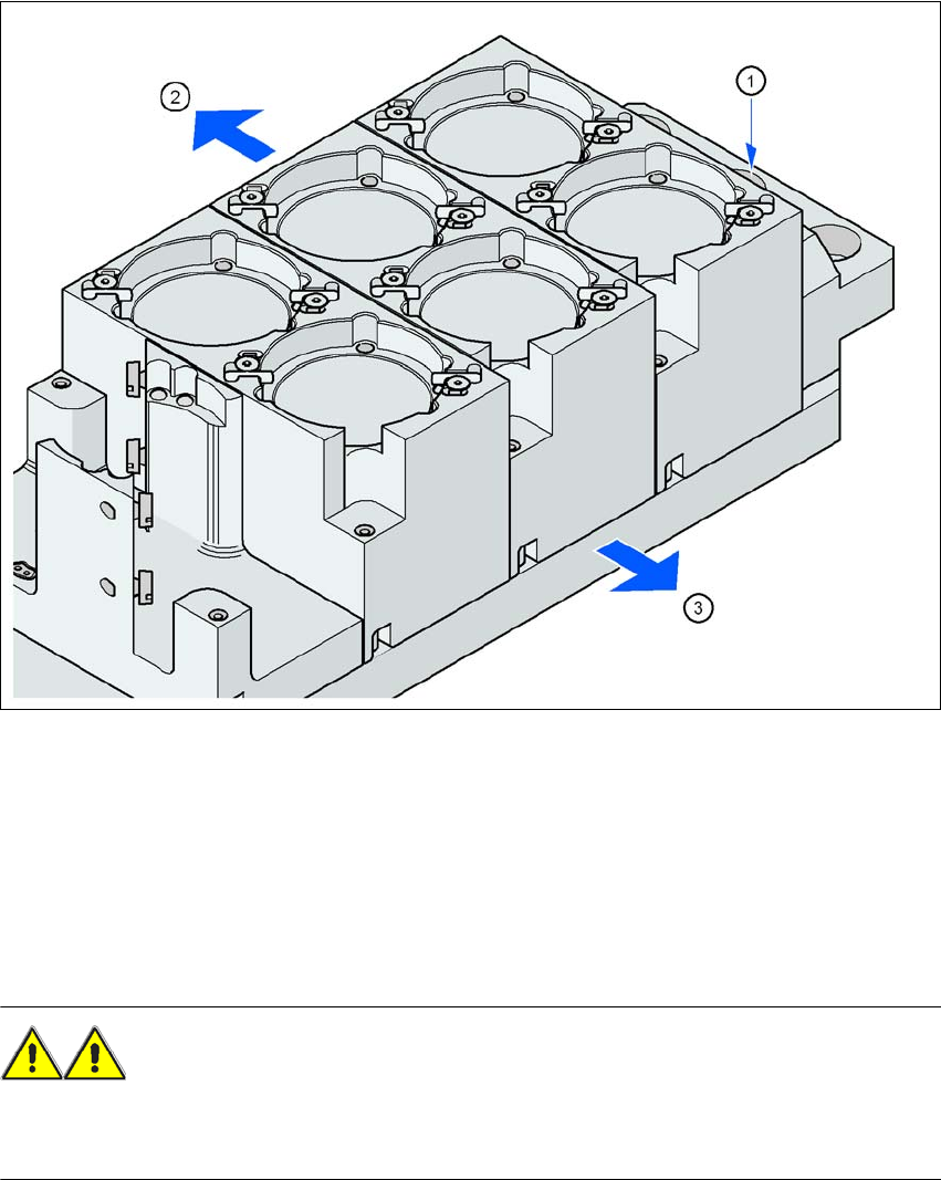
6.1.3.4 Assembly
The nozzle changer is fixed to the component trolley docking unit.
6
Fig. 6.1 - 15 Assembly position
(1) Marking hole
(2) Operator side
(3) Arrow pointing toward the PCB conveyor
6
Align the nozzle changer so that the marking hole (item 1) is on the left, as viewed by the op-
erator.
WARNING 6
– Only install the corresponding nozzle changers for each placement head. There is a risk of
head crashes with mixed configurations.
User Manual SIPLACE SX4/DX4 6 Station extensions
From software version SC.706.xx Version 06/2012 EN 6.1 Nozzle changer
313
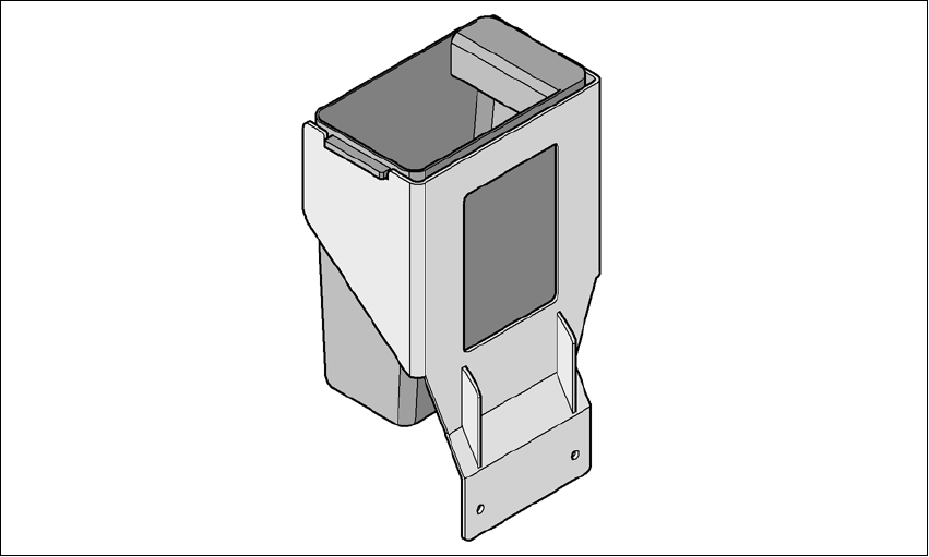
6.1.3.5 Component reject bin for the SIPLACE TwinStar
A component reject bin can be installed for the SIPLACE TwinStar. This is positioned next to the
stationary camera.
6
Fig. 6.1 - 16 Component reject bin for the SIPLACE TwinStar
6.1.3.6 Grippers and special nozzles
The SIPLACE machines can process components based on through hole technology and odd-
shaped (OSC) components, in addition to the standard SMT spectrum. ASM also continuously de-
velops special nozzles and grippers.
Special nozzles are available for all placement heads in order to process placement jobs with max-
imum speed, precision and flexibility. The use of automatic nozzle changers also reduces the
setup times that occur at a product change.
ASM can provide mechanical grippers for Pick&Place heads. If a component's surface is not suit-
able for sucking up with nozzles, then it can be picked up and placed with mechanical grippers.
There are two types of gripper and their functions can be divided into two groups:
– Grippers that grip the component at its outer edges and
– Grippers that grip the component at its inner edge.
Information on special nozzles and grippers is available from ASM. For the production of special
magazines and grippers, again contact ASM.
6 Station extensions User Manual SIPLACE SX4/DX4
6.2 DX changeover tables on the SIPLACE DX4 From software version SC.706.xx Version 06/2012 EN
314
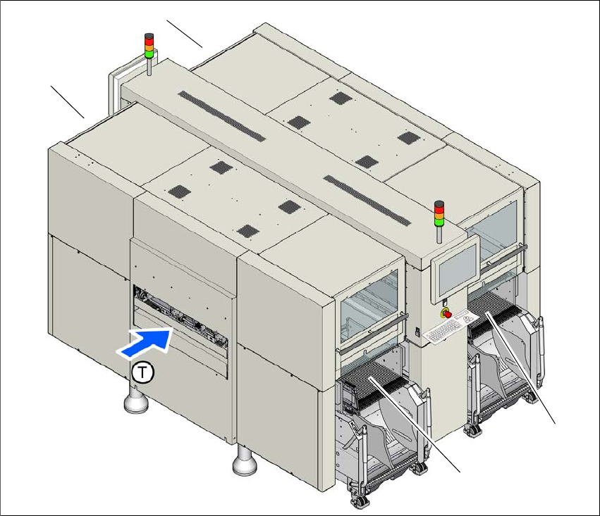
6.2 DX changeover tables on the SIPLACE DX4
Item no. 03089820-xx DX changeover table SIPLACE DX4 with 40/2 tracks
Item no. 03089961-xx DX changeover table docking unit for 40/2 tracks
Just like the fixed DX tables, the DX changeover tables are optimized for the use of 2x8 mm SI-
PLACE tape feeder modules when using 8 mm tapes. By using 20 of these feeder modules, you
can achieve a full setup capacity of 40 8mm tracks. The design and function of the DX changeover
tables is basically identical to that of the component changeover tables for the SIPLACE SX4 ma-
chines. See “SIPLACE X series changeover table” on page 181.
6
Fig. 6.2 - 1 DX changeover table locations, SIPLACE DX4
(1) Location 1
(2) Location 2
(3) Location 3
(4) Location 4
(T) Direction of PCB transport
(1)
(4)
(2)
(3)