00196693-03_UM_SX4DX4_SR706_EN.pdf - 第181页
User Manual SIPLACE SX4/DX4 3 Technical data and assemblies From software version SC.706.xx V ersion 06/2012 EN 3.10 Component trolleys on the SIPLACE SX4 181 3.10.6 SIPLACE X series changeover t able The front slider gu…
3 Technical data and assemblies User Manual SIPLACE SX4/DX4
3.10 Component trolleys on the SIPLACE SX4 From software version SC.706.xx Version 06/2012 EN
180
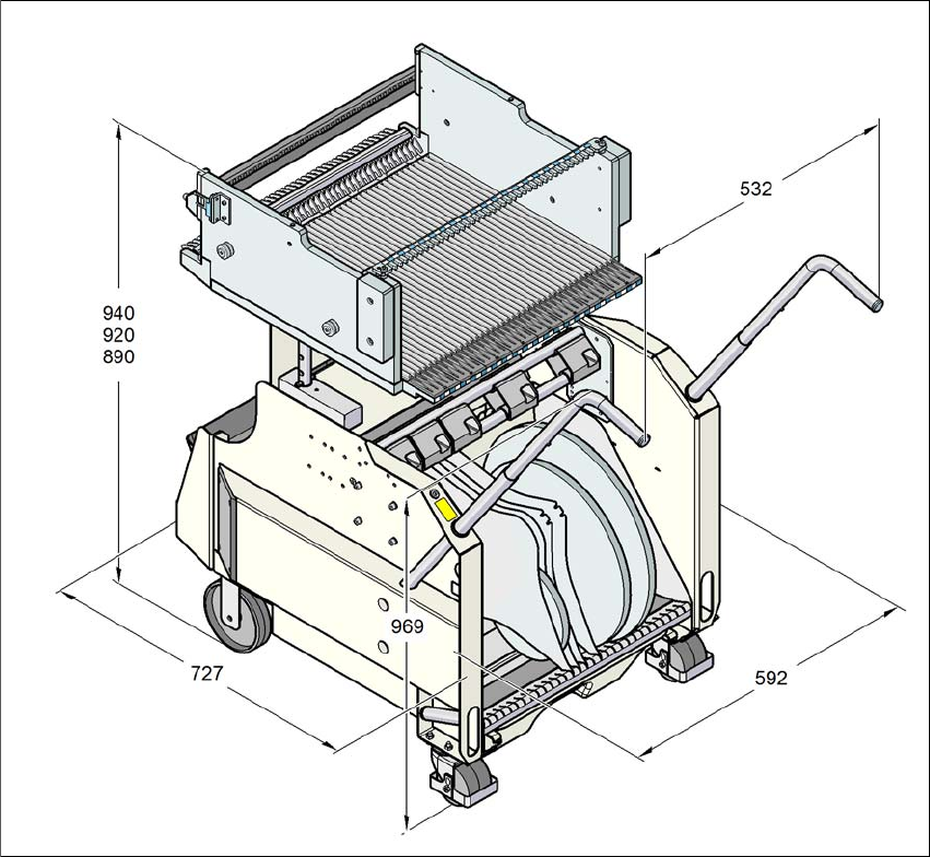
3.10.5 Dimensions of SIPLACE X series component trolley
3
Fig. 3.10 - 5 Dimensions of the SIPLACE X series component trolley; all dimensions in millimeters
User Manual SIPLACE SX4/DX4 3 Technical data and assemblies
From software version SC.706.xx Version 06/2012 EN 3.10 Component trolleys on the SIPLACE SX4
181
3.10.6 SIPLACE X series changeover table
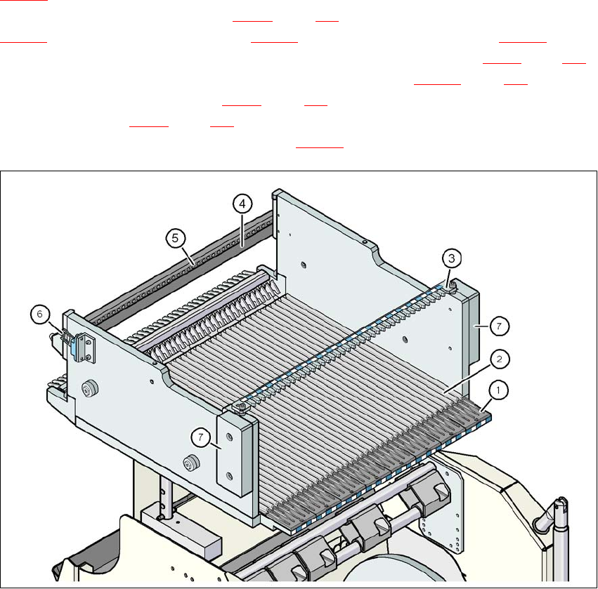
The front slider guides of the feeder modules are placed on the insertion aid (item 1 in fig.
3.10 - 6
). When pushed in, the slider guides of the
feeder module (item 12 and 13 in fig. 3.9 - 2
, page 151) slide on the guide profile (item 2 in fig.
3.10 - 6
) up to the stop rail (item 4 in fig. 3.10 - 6). A centering hole (item 5 in fig. 3.10 - 6) on the
stop rail accommodates the X feeder module centering pin "front" (item 4 in fig. 3.9 - 1
, page 150).
At the same time, the changeover table locking latch (item 1 in fig. 3.10 - 7
, page 182) engages
onto the locking roller (item 1 in fig. 3.9 - 1
, page 150) of the feeder module. The centering pin
"rear" (item 12 in fig. 3.9 - 1
, page 150) on the upper side of the feeder module is accommodated
by the recess in the centering bar (item 3 in fig. 3.10 - 6
).
3
Fig. 3.10 - 6 Changeover table, SIPLACE X series, rear view
(1) Insertion aid
(2) Guide profile ( profile)
(3) Centering bar for holding the "back" centering pin for X feeder modules
(4) Stop bar
(5) Centering holes
(6) Contact for switching the safety switch of the EMERGENCY STOP circuit
(7) Hand guard
3 Technical data and assemblies User Manual SIPLACE SX4/DX4
3.10 Component trolleys on the SIPLACE SX4 From software version SC.706.xx Version 06/2012 EN
182
3
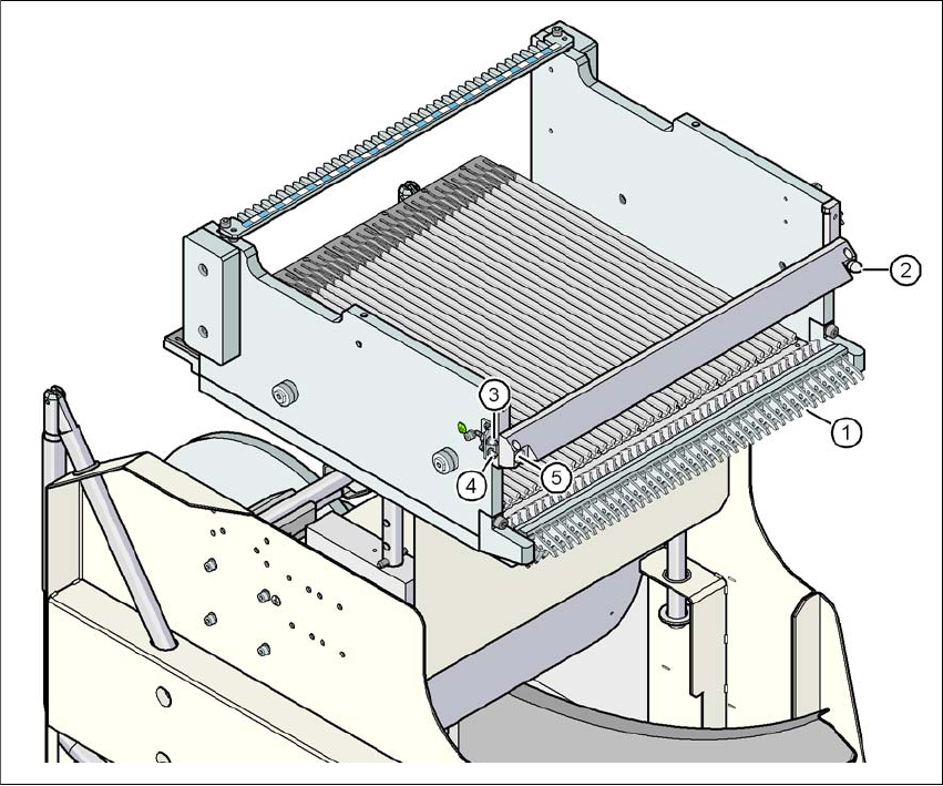
Fig. 3.10 - 7 SIPLACE X series changeover table, front view
(1) Locking latches
(2) Centering pin on the changeover table
(3) compressed air coupling
(4) Earthing (ground) pin
(5) Centering hole on the changeover table