00196693-03_UM_SX4DX4_SR706_EN.pdf - 第115页
User Manual SIPLACE SX4/DX4 3 Technical data and assemblies From software version SC.706.xx Version 06/2012 EN 3.5 Placement head 115 3.5.1.3 T echnical data wit h component camera, type 41 3 3.5.1.4 Sensor for the comp …

3 Technical data and assemblies User Manual SIPLACE SX4/DX4
3.5 Placement head From software version SC.706.xx Version 06/2012 EN
114
3.5.1.2 Technical data with component camera, type 23 (default)
3
Component range
a
a) Please note that the component range that can be placed is also affected by the pad geometry, the custom-
er-specific standards and the packaging tolerances.
01005 to 2220, Melf, SOT, SOD
Component specification
max. height
min. lead pitch
min. lead width
min. ball pitch
min. ball diameter
min. dimensions
max. dimensions
max. weight
4 mm
0.25 mm
0.1 mm
0.4 mm
0.2 mm
0.4 mm x 0.2 mm
6 mm x 6 mm
1 g
Programmable set-down force, variable increments 1.5 N to 4.5 N
Nozzle types 10xx, 11xx, 12xx
X/Y accuracy
b
b) The accuracy value, measured using the vendor-neutral IPC standard.
± 41 μm/3, ± 55 μm/4
Angular accuracy ± 0.5°/3± 0.7°/4
Component range 95%
Illumination level 5
Possible illumination level settings 256
5
User Manual SIPLACE SX4/DX4 3 Technical data and assemblies
From software version SC.706.xx Version 06/2012 EN 3.5 Placement head
115
3.5.1.3 Technical data with component camera, type 41
3
3.5.1.4 Sensor for the component reject bin
PLEASE NOTE 3
When using a SpeedStar we recommend that you install the optional sensor for the component
reject bin. (See also section 6.6, page 330)
Component range
a
a) Please note that the component range that can be placed is also affected by the pad geometry, the customer-spe-
cific standards and the packaging tolerances.
01005 to 2220, Melf, SOT, SOD,
Bare-Die, Flip-Chip
Component specification
max. height
min. lead pitch
min. lead width
min. ball pitch
min. ball diameter
min. dimensions
max. dimensions
max. weight
4 mm
0.08 mm
0,03 mm
0,10 mm
0.05 mm
0.12 mm x 0.12 mm
6 mm x 6 mm
1 g
Programmable set-down force, variable increments 1.5 N to 4.5 N
Nozzle types 10xx, 11xx, 12xx
X/Y accuracy ± 41 μm/3, ± 55 μm/4
Angular accuracy ± 0.5°/3± 0.7°/4
Illumination level 5
Possible illumination level settings 256
5
3 Technical data and assemblies User Manual SIPLACE SX4/DX4
3.5 Placement head From software version SC.706.xx Version 06/2012 EN
116
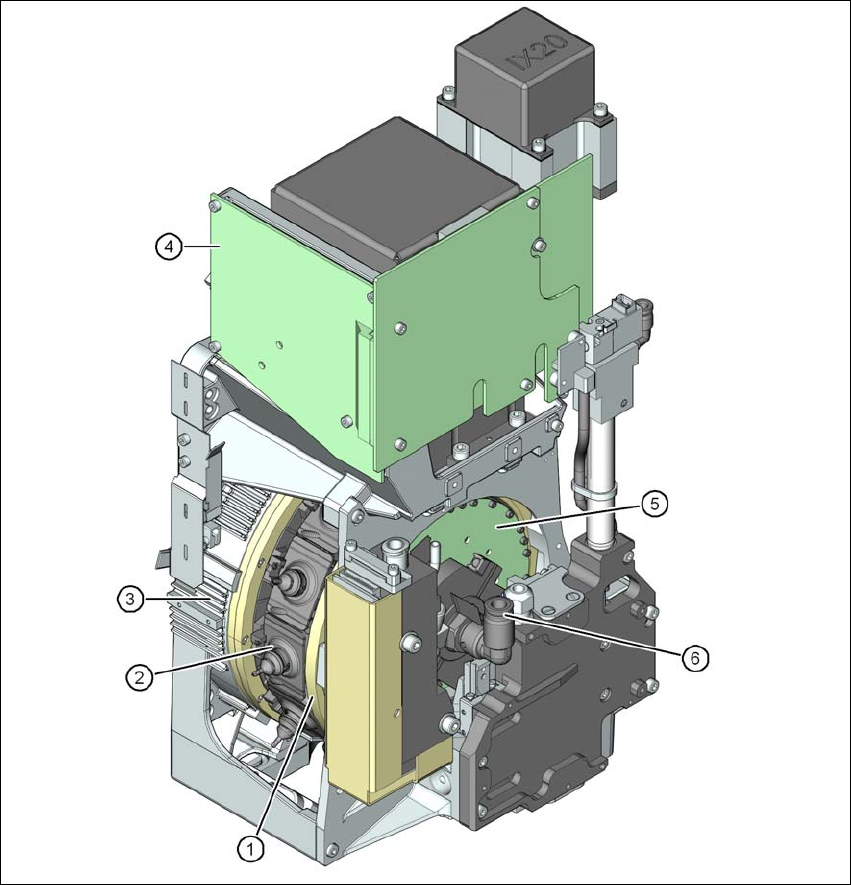
3.5.2 SIPLACE MultiStar CPP (SX4 only)
3
Fig. 3.5 - 3 SIPLACE MultiStar - front view, function groups part 1
(1) Star with 12 segments
(2) Segment with integrated DP drive
(3) Torque motor for star drive
(4) intermediate distributor board
(5) Control board for 12 DP drives
(6) Compressed air connection for the Venturi nozzles in the pickup/placement and holding cir-
cuit