00196693-03_UM_SX4DX4_SR706_EN.pdf - 第79页
User Manual SIPLACE SX4/DX4 2 Operational safety From software version SC.706.xx Version 06/2012 EN 2.8 Re sidual voltages and discharge times in the machine 79 Fig. 2.8 - 2 Measuring point X200 on the power supply unit …
2 Operational safety User Manual SIPLACE SX4/DX4
2.8 Residual voltages and discharge times in the machine From software version SC.706.xx Version 06/2012 EN
78
2.8 Residual voltages and discharge times in the machine
If the EMERGENCY STOP button is pressed or the machine is switched off, the 260 VDC link volt-
age for the gantry axes and the 150 VDC link voltage for the star axes are reduced to harmless
residual voltages in a very short time.
WARNING 2
The machine is supplied with 3 x 200 V~, 3 x 208 V~, 3 x 220 V~, 3 x 230 V~, 3 x 380 V~,
3x400V~ or 3x415V~ ± 5%, 50/60Hz mains voltage. This means that some parts of the sys-
tem carry potentially lethal voltages - even when switched off at the main power switch. Incorrect
handling of the machine can therefore result in death or severe injury or considerable damage to
equipment.
Always follow the applicable accident prevention and DIN regulations (particularly EN 60204,
part 1 or IEC 60204, part 1) and the applicable regulations in your own country.
The covers over the power supply unit may ONLY be opened by appropriately qualified and
trained personnel.
2
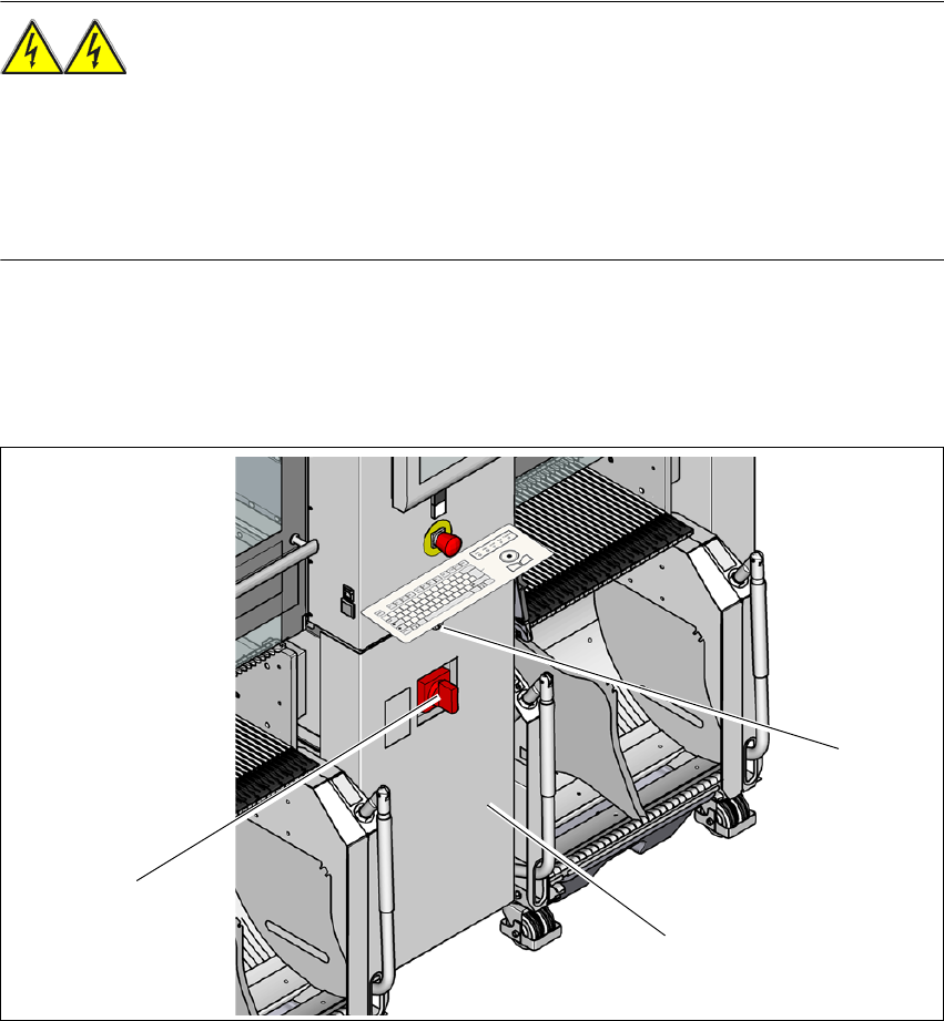
Fig. 2.8 - 1 Power supply unit (example of SX4)
(1) Main power switch
(2) Power supply unit behind the cover
(3) Padlock with bolt in the cover
(3)
(1)
(2)
User Manual SIPLACE SX4/DX4 2 Operational safety
From software version SC.706.xx Version 06/2012 EN 2.8 Residual voltages and discharge times in the machine
79
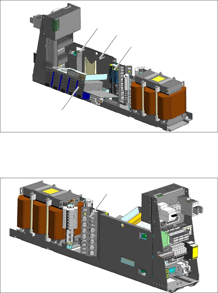
Fig. 2.8 - 2 Measuring point X200 on the power supply unit
(1) Distributor terminal block X200
In order to access the X200 terminal strip, both fastening screws (2) on the service flap (3) must
be loosened and the flap folded down.
2
Fig. 2.8 - 3 Interface-machine cable tree on the power supply unit
(1) Interface-machine cable tree
(1)
(2)
(2)
(3)
(1)

2 Operational safety User Manual SIPLACE SX4/DX4
2.8 Residual voltages and discharge times in the machine From software version SC.706.xx Version 06/2012 EN
80
2.8.1 Residual voltages and discharge times after switching off the main switch
2
Measuring point on the X200
distributor terminal block
Voltage in
normal mode
Residual voltage if
main switch OFF or
power failure
Discharge
times
X200 - 1.a 260 V- < 10 VDC < 2s
X200 - 4.a 150 V- < 10 VDC < 2s
X200 - 17.a 42 V- (permanent) < 10 VDC < 2s
X200 - 17.a 42 V- (switched) < 10 VDC < 2s
X200-13.a 24 V- < 10 VDC < 2s
Interface-machine cable tree Voltage in
normal mode
Residual voltage if
main switch OFF or
power failure
Discharge
times
X21 - 1 260 V- < 10 VDC < 2s
X31 - 1 150 V- < 10 VDC < 2s
A8 ( positive connection) 42 V- (permanent) < 10 VDC < 2s
X18 - 7 42 V- (switched) < 10 VDC < 2s
X17 - 1 24 V- < 10 VDC < 2s