00196693-03_UM_SX4DX4_SR706_EN.pdf - 第340页
6 Station extensions User Manual SIPLACE SX4/DX4 6.15 Vision Teach Station From software version SC.706.xx Version 06/2012 EN 340 6.15.1 Description The vision teach station is a system for c reating and testing package …
User Manual SIPLACE SX4/DX4 6 Station extensions
From software version SC.706.xx Version 06/2012 EN 6.15 Vision Teach Station
339
6.15 Vision Teach Station
Item no. 00119788-xx Vision teach station
6
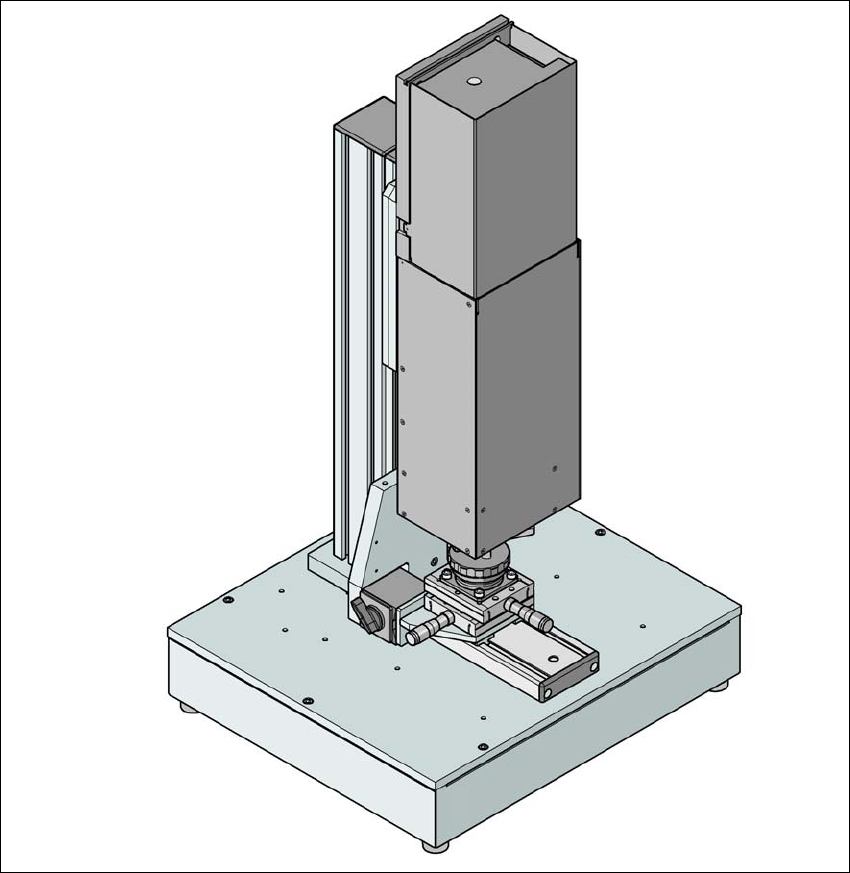
Fig. 6.15 - 1 Vision teach station with component camera, type 33
6 Station extensions User Manual SIPLACE SX4/DX4
6.15 Vision Teach Station From software version SC.706.xx Version 06/2012 EN
340
6.15.1 Description
The vision teach station is a system for creating and testing package form descriptions for com-
ponents to be processed on SIPLACE placement machines.
The vision teach station essentially consists of the following components:
– Base module with electronic circuits and one or two component cameras
– Mini-tower PC
WINDOWS XP operating system 6
SIPLACE Vision image processing software 6
SIPLACE Pro database server 6
Camera interfaces: CAN bus card and camera bus card 6
The vision teach station is used to create and test descriptions for package forms for any place-
ment machine and to run component inspections.
The package form descriptions thus created may be stored in the SIPLACE Pro database on the
vision teach station and transferred to the SIPLACE Pro database of the production system. You
can also download vision screenshots from placement machines to the vision teach station for
analysis. Only multiple component measurements still have to be carried out on the placement
machine.
6.15.2 Advantages
The major advantage of this offline system is that it is totally independent of the production system,
and no production system resources have to be used for creating and testing package form de-
scriptions. As a result, there is no loss of productivity due to the description and testing of package
forms. The time taken to introduce new products can also be considerably reduced with this inde-
pendent system.

User Manual SIPLACE SX4/DX4 Index
Version 06/2012 EN
341
Index
Symbols
"Head crash" label
. . . . . . . . . . . . . . . . . . . . . . .52
"Switching on the SIPLACE line" flow chart
. . .243
Numerics
12 mm X tape feeder module
. . . . . . . . . . . . . .154
16 mm X tape feeder module
. . . . . . . . . . . . . .156
1D board barcode readers
. . . . . . . . . . . . . . . .318
24 mm X tape feeder module
. . . . . . . . . . . . . .158
2D board code reader
. . . . . . . . . . . . . . . . . . . .318
2x8 mm X tape feeder module
. . . . . . . . . . . . .152
32 mm X tape feeder module
. . . . . . . . . . . . . .159
44 mm X tape feeder module
. . . . . . . . . . . . . .160
56 mm X tape feeder module
. . . . . . . . . . . . . .161
72 mm X tape feeder module
. . . . . . . . . . . . . .162
8 mm X tape feeder module
. . . . . . . . . . . . . . .153
88 mm X tape feeder module
. . . . . . . . . . . . . .163
A
abbreviations
. . . . . . . . . . . . . . . . . . . . . . . . . . . .30
activities at shift change
. . . . . . . . . . . . . . . . . .262
adapter for the X series feeder modules
.170, 171,
172
adapter plate for label presenter
. . . . . . . . . . . .170
adapter plate for reject conveyor
. . . . . . . . . . .172
adapter plate, 16.5 mm
. . . . . . . . . . . . . . . . . . .171
adapting the component trolley to the PCB conveyor
height
. . . . . . . . . . . . . . . . . . . . . . . . . . . . .228
Adjusting the empty tape duct to the component
height
. . . . . . . . . . . . . . . . . . . . . . . . . . . . .230
Advanced production
. . . . . . . . . . . . . . . . . . . .241
air cushion transport system
. . . . . . . . . . 211, 226
Alert
. . . . . . . . . . . . . . . . . . . . . . . . . . . . . . . . . .253
alert information, colors
. . . . . . . . . . . . . . . . . . .256
Allen wrench, size 10
. . . . . . . . . . . . . . . . . . . .211
Allen wrench, size 19
. . . . . . . . . . . . . . . . . . . .211
ambient conditions
ambient pressure
. . . . . . . . . . . . . . . . . . . .101
ambient conditions for the packaging, transportation
and storage
. . . . . . . . . . . . . . . . . . . . . . . .103
ambient pressure
. . . . . . . . . . . . . . . . . . . . . . .101
angular accuracy
. . . . . . . . . . . . . . . . . . . . . 96, 97
A-Placement
. . . . . . . . . . . . . . . . . . . . . . . . . . . 30
assembly position for the stationary cameras
IC and FC camera
. . . . . . . . . . . . . . . . . . 143
Assembly positions of MultiStar in the machine
121
assembly positions of SIPLACE MultiStar
. . . 119
Atmospheric humidity
. . . . . . . . . . . . . . . . . . . 101
authorized accessories
. . . . . . . . . . . . . . . . . . . 23
authorized employees.
. . . . . . . . . . . . . . . . . . . 92
automatic circuit breaker F1
. . . . . . . . . . . . . . . 87
automatic width adjustment
. . . . . . . . . . . . . . . 139
avoiding track errors
. . . . . . . . . . . . . . . . . . . . 286
B
basic view
. . . . . . . . . . . . . . . . . . . . . . . . . . . . 248
Boards being processed
. . . . . . . . . . . . . . . . . 247
button for releasing the locking latch
. . . . . . . . 173
buttons
. . . . . . . . . . . . . . . . . . . . . . . . . . . . . . . 66
C
C&P component camera, type 30, 27 x 27, digital
143
camera amplifier
. . . . . . . . . . . . . . . . . . . . 143
camera lens
. . . . . . . . . . . . . . . . . . . . . . . 143
component dimensions
. . . . . . . . . . . . . . . 143
Component range
. . . . . . . . . . . . . . . . . . . 143
field of vision
. . . . . . . . . . . . . . . . . . . . . . . 143
illumination
. . . . . . . . . . . . . . . . . . . . . . . . 143
illumination control
. . . . . . . . . . . . . . . . . . 143
Method of illumination
. . . . . . . . . . . . . . . . 143
min. ball diameter
. . . . . . . . . . . . . . . . . . . 143
min. ball pitch
. . . . . . . . . . . . . . . . . . . . . . 143
min. lead pitch
. . . . . . . . . . . . . . . . . . . . . 143
min. lead width
. . . . . . . . . . . . . . . . . . . . . 143
C&P20
. . . . . . . . . . . . . . . . . . . . . . . . . . . . . . . . 30
calibrate machine
. . . . . . . . . . . . . . . . . . . . . . 249
carrying out a setup check
. . . . . . . . . . . . . . . 262
carrying out a sight check
. . . . . . . . . . . . . . . . 264
center of gravity
. . . . . . . . . . . . . . . . . . . . . . . . 108
center of gravity coordinates
. . . . . . . . . . . . . . 108
centering bar for holding the "back" centering pin for
X feeder module
. . . . . . . . . . . . . . . . . . . . 181
Centering holes, SIPLACE X series changeover ta-
ble
. . . . . . . . . . . . . . . . . . . . . . . . . . . 181, 182