00196693-03_UM_SX4DX4_SR706_EN.pdf - 第322页
6 Station extensions User Manual SIPLACE SX4/DX4 6.5 Docking station for the component trolley of the SIPLACE X se ries From software version SC.706.xx Version 0 6/2012 EN 322 Legend for fig. 6.5 - 1 , page 321 (1) Docki…
User Manual SIPLACE SX4/DX4 6 Station extensions
From software version SC.706.xx Version 06/2012 EN 6.5 Docking station for the component trolley of the SIPLACE X series
321
6.5 Docking station for the component trolley of the
SIPLACE X series
Item no. 00116933-xx docking station for SIPLACE X component trolley
PLEASE NOTE:
A docking station (multi docking station) with which component trolleys can be configured for 30,
40 and 60 tracks is available on request. 6
6.5.1 Description
The docking station is an additional component for the setup area. It forms the link between the
setup area and the component trolley for the SIPLACE X series. The docking station allows the
component trolleys to be set up with feeder modules and function tests and setup checks to be
carried out externally.
6
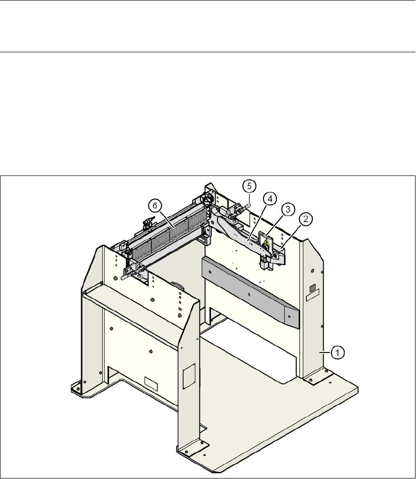
Fig. 6.5 - 1 Docking station, SIPLACE X series

6 Station extensions User Manual SIPLACE SX4/DX4
6.5 Docking station for the component trolley of the SIPLACE X series From software version SC.706.xx Version 06/2012 EN
322
Legend for fig. 6.5 - 1, page 321
(1) Docking station
(2) X series component trolley docking unit
(3) Protective plate with warning sign W204
(4) Rails for guiding and docking the changeover table
(5) Clamping lever for locking the component trolley
(6) EDIF (energy and data interface)
The main tasks performed by the docking station are as follows:
– Supply of energy to the component trolley and X feeder modules
– Supply of compressed air to the component trolley and X feeder modules
– Provision of an infrastructure for communication between the pre-setup location PC and
the feeder modules
With the help of the docking station, the operator can perform function tests to the X feeder mod-
ules outside the production environment and can check the setup. There are two rows, each with
four docking stations, connected via the CAN bus of the pre-setup PC. Each docking station has
its own power and compressed air connection.
The component trolley docking unit (item 2 in fig. 6.5 - 1
, page 321) for the docking station can be
adjusted to the required PCB conveyor height. To perform the pre-setup tasks, the component trol-
ley is pushed into the docking station (item 1 in fig. 6.5 - 1
, page 321). The component trolley slides
along the docking unit rails, with the roller bearings on the side of the component trolley, up to the
energy and data interface connection. The changeover table with the feeder module EDIF is po-
sitioned precisely in relation to the EDIF (item 5 in fig. 6.5 - 1
, page 321) of the component trolley
docking unit and fixed in this position with the two clamping levers. The protective plates (item 3
in fig. 6.5 - 1
, page 321) prevent access to the component trolley rollers, once these are pushed
into the docking station.
User Manual SIPLACE SX4/DX4 6 Station extensions
From software version SC.706.xx Version 06/2012 EN 6.5 Docking station for the component trolley of the SIPLACE X series
323
6
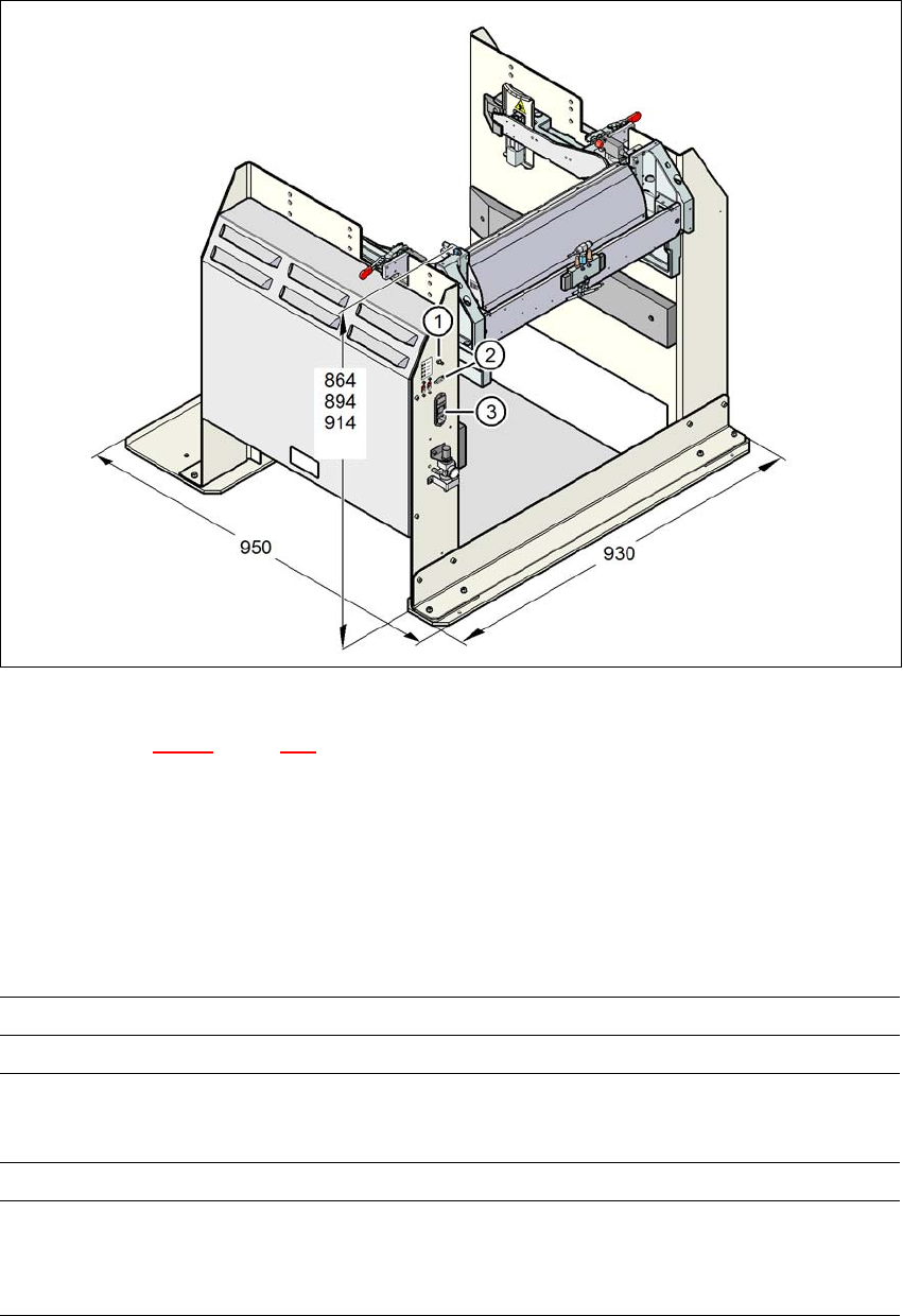
Fig. 6.5 - 2 Docking station - dimensions in millimeters, connection points
Legend for fig. 6.5 - 2, page 323
(1) Compressed air connection
(2) CAN bus connection
(3) Power supply connection
6.5.2 Technical data
6
Dimensions
Length x width 950 mm x 930 mm
Height 864 mm for 900 mm PCB conveyor height
894 mm for 930 mm PCB conveyor height
914 mm for 950 mm PCB conveyor height
Weight 120 kg
Compressed air pressure val-
ues
p
min
p
max
0.5 MPa (5.0 bar)
1.0 MPa (10.0 bar)