00196693-03_UM_SX4DX4_SR706_EN.pdf - 第126页
3 Technical data and assemblies User Manual SIPLACE SX4/DX4 3.5 Placement head From software version SC.706.xx Version 06/2012 EN 126 3.5.3 SIPLACE T winSt ar for high precision IC placement (SX4 only) 3 Fig. 3.5 - 9 SIP…
User Manual SIPLACE SX4/DX4 3 Technical data and assemblies
From software version SC.706.xx Version 06/2012 EN 3.5 Placement head
125
3.5.2.9 Technical data for SIPLACE MultiStar (CPP)
3
SIPLACE MultiStar
component camera type 30 (CPP)
SIPLACE MultiStar
component camera type 33 (CPP)
Component range
a
a) Please note that the placeable component range is also affected by the pad geometry, the customer-spe-
cific standards, the component packaging tolerances and the component tolerances.
01005 to 27 mm x 27 mm 0402 to 50 mm x 40 mm
Component spec.
max height
b
max. height
c
min. lead pitch
min. lead width
min. ball pitch
min. ball diameter
min. dimensions
max. dimensions
max. weight
b) CPP head: in low installation position (stationary component camera not possible).
c) CPP head: in high installation position
6.0 mm
8.5 mm
0.3 mm
0.15 mm
0.25 mm
d
0.35 mm
e
0.14 mm
d
0.20 mm
e
0.4mm x 0.2mm
27 mm x 27 mm
4 g
d) For components < 18 mm x 18 mm
e) For components ≥ 18 mm x18 mm
11.5 mm
0.3 mm
0.15 mm
0.35 mm
0.2 mm
1.0 mm x 0.5 mm
50 mm x 40 mm
8 g
Programmable set-down
force
1.0 - 10 N 1.0 - 10 N
Nozzle types 20xx, 28xx 20xx, 28xx
X/Y accuracy
f
f) The accuracy value, measured using the vendor-neutral IPC standard.
± 41 µm/3
± 55 µm/4
± 34 µm/3
± 45 µm/4
Angular accuracy ± 0.4° / 3
g
, ± 0.5° / 3
h
± 0.5° / 4
g
, ± 0.7° / 4
h
g) Component dimensions between 6 mm x 6 mm and 27 mm x 27 mm.
h) Component dimensions smaller than 6 mm x 6 mm.
± 0.2° / 3
± 0.3° / 4
Illumination level 5 6
Possible illumination
level settings
256
5
256
6
3 Technical data and assemblies User Manual SIPLACE SX4/DX4
3.5 Placement head From software version SC.706.xx Version 06/2012 EN
126
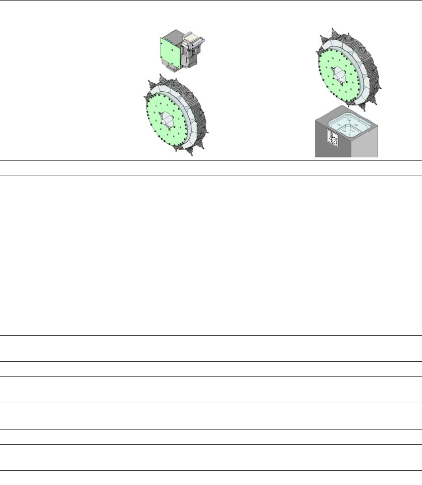
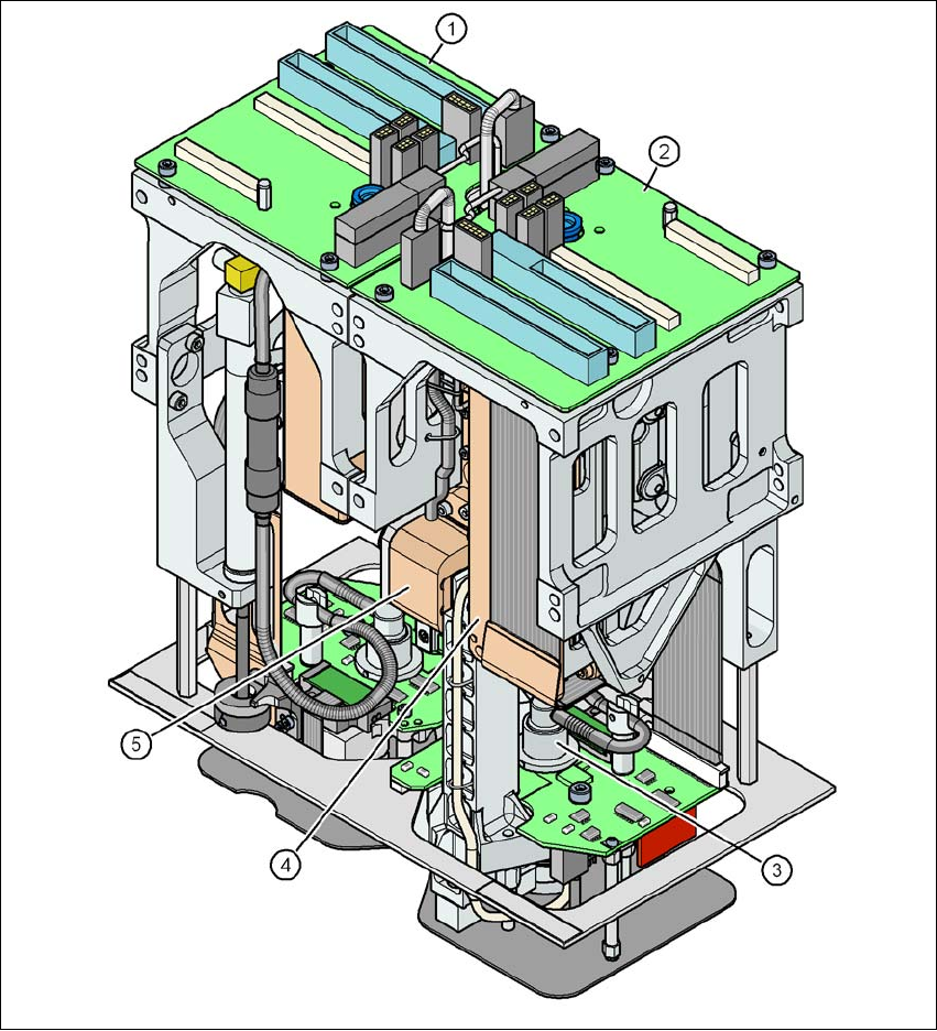
3.5.3 SIPLACE TwinStar for high precision IC placement (SX4 only)
3
Fig. 3.5 - 9 SIPLACE TwinStar for high precision IC placement
3
(1) Pick&Place module 1 (P&P1) - the TwinStar consists of 2 Pick&Place modules
(2) Pick&Place module 2 (P&P2)
(3) DP axis
(4) Z axis drive
(5) Incremental distance measuring system for the Z axis
User Manual SIPLACE SX4/DX4 3 Technical data and assemblies
From software version SC.706.xx Version 06/2012 EN 3.5 Placement head
127
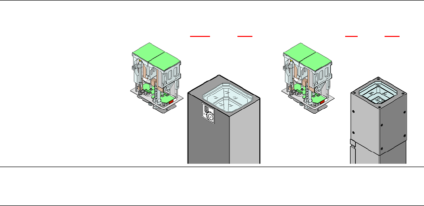
3.5.3.1 Description
This sophisticated placement head consists of two placement heads of the same type coupled to-
gether. Both heads work using the Pick&Place principle. The TwinStar is suitable for processing
complex and large components. Two components are picked up by the placement head, optically
centered on the way to the placement position and rotated into the necessary placement angle.
They are then placed gently and accurately onto the PCB with a controlled blast of air.
New nozzles (type 5xx) have been developed for the TwinStar. With an adapter you can also use
the nozzles of type 4xx from the Pick&Place head and nozzles of type 8xx and 9xx from the Col-
lect&Place heads.
3.5.3.2 Technical data
Optical centering with Stationary P&P component camera
(type 33) 55 x 45, digital
(see section 3.8.3
, page 144)
Stationary P&P component camera
(type 25) 16 x 16, digital
(see section 6.8, page 332)
Component range
a
0402 to SO, PLCC, QFP, BGA, spe-
cial components, bare dies, flip-
chips
0201 to SO, PLCC, QFP, sockets,
plugs, BGA, special components,
bare dies, flip-chips, shields