00196693-03_UM_SX4DX4_SR706_EN.pdf - 第18页
1 Introduction User Manual SIPLACE SX4/DX4 1.2 SIPLACE DX4 From software version SC.706.xx Version 06/2012 EN 18 1.2 SIPLACE DX4 1 Fig. 1.2 - 1 SIPLACE DX4 placement machine The SIPLACE DX4 placement machine h as the fol…

User Manual SIPLACE SX4/DX4 1 Introduction
From software version SC.706.xx Version 06/2012 EN 1.1 SIPLACE SX4
17
Three placement methods are possible for processing the components:
– Collect&Place,
– Pick&Place and
– A combination of Collect&Place and Pick&Place (mixed mode).
The SIPLACE SX4 placement machine has four gantries. The head modularity principle devel-
oped by SIPLACE allows you to change placement heads quickly and easily. For an overview of
the placement head configuration, refer to section 1.1.1
from page 17.
These can be quickly and accurately positioned by linear motors, moving independently of one
another in the X and Y directions.
There are four locations available for supplying components. These can be fitted with component
trolleys and configured with up to 40 tracks.
1.1.1 Overview of placement head configuration
1
CPP_H = Multistar CPP in high assembly position
Placement area 1 Placement area 2
C&P20 / C&P20 C&P20 / C&P20
C&P20 / C&P20 CPP / CPP
C&P20 / C&P20 TH / TH
C&P20 / C&P20 CPP_H/TH
CPP / CPP CPP / CPP
CPP / CPP CPP_H/TH
CPP / CPP TH / TH
1 Introduction User Manual SIPLACE SX4/DX4
1.2 SIPLACE DX4 From software version SC.706.xx Version 06/2012 EN
18
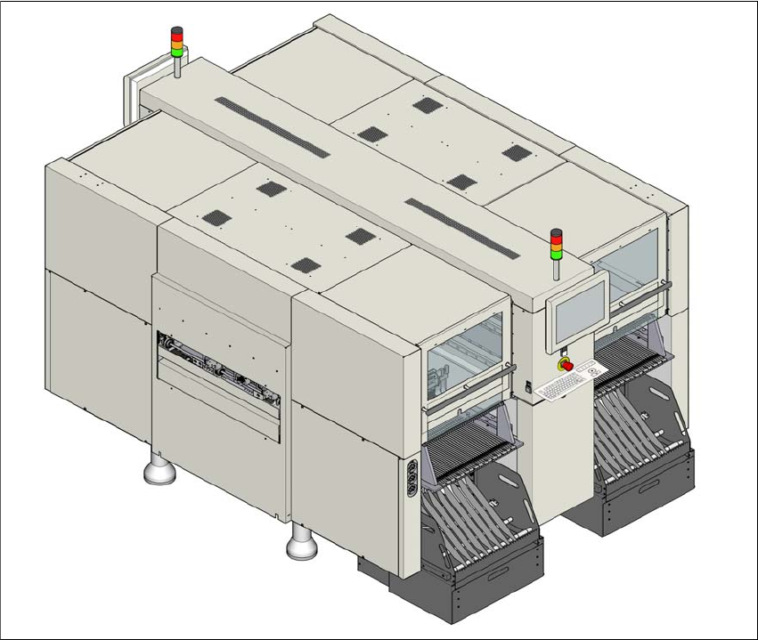
1.2 SIPLACE DX4
1
Fig. 1.2 - 1 SIPLACE DX4 placement machine
The SIPLACE DX4 placement machine has the following distinguishing features:
– High precision,
– Intelligent placement optimization,
– Intelligent configuration strategies,
– Placement performance up to the high end process range
The Collect&Place procedure is used for processing the components.
The SIPLACE DX4 placement machine has four gantries. These can be quickly and accurately
positioned by linear motors, moving independently of one another in the X and Y directions.
There are four locations with DX tables available for supplying components. These can be config-
ured with up to 40 tracks.

User Manual SIPLACE SX4/DX4 1 Introduction
From software version SC.706.xx Version 06/2012 EN 1.3 Machine description
19
1.2.1 Overview of placement head configuration
1
1.3 Machine description
1.3.1 The SIPLACE principle
The placement heads pick up the components from the feeder modules (fixed position) on the
component trolleys or DX tables and then place the waiting boards.
The SIPLACE SX4 placement machine has two placement areas and a dual conveyor. Two
boards can be placed at the same time on dual conveyors.
The SIPLACE DX4 placement machine has two placement areas and a single conveyor.
The principle of "stationary component supply" and "stationary PCB", which have proven them-
selves in the other SIPLACE machines, offer a range of decisive benefits:
– Refilling components and splicing on tapes does not cause downtime.
– The vibration-free component feeder means that even the smallest components (e.g. 01005)
are picked up reliably.
– The PCB, which does not move during the placement process, prevents the components slip-
ping.
– The combination of placement heads with nozzle changers always guarantees an optimum
nozzle configuration for every placement process, thus minimizing traversing paths and opti-
mizing the placement sequence.
High flexibility, efficiency and reliable setups are the guarantee for top productivity in the SIPLACE
machines.
Minimum down times increase utilization and thus help to increase productivity.
Placement area 1 Placement area 2
C&P20 / C&P20 C&P20 / C&P20