00196693-03_UM_SX4DX4_SR706_EN.pdf - 第212页
4 Setting up and commissioning User Manual SIPLACE SX4/DX4 4.3 Setting up the machine From software version SC.706.xx Version 06/2012 EN 212 4.3.6 Presetting board conveyor height Push the forks of the fork lif t unde …
User Manual SIPLACE SX4/DX4 4 Setting up and commissioning
From software version SC.706.xx Version 06/2012 EN 4.3 Setting up the machine
211
4.3.5 Tools and equipment
You will need the following tools and equipment to adjust the height of your machine:
You will need the following tools and equipment to adjust the height of your machine:
– Fork wrench SW 36, Item no. 00096286-01
– Wrench of width 36 for the setting screw M24x2x120 used to adjust the height of the machine
feet.
– Hook wrench 135 - 145 for adjusting the middle machine feet,
Item no. 00376519-xx
– Single head wrench SW 65, Item no. 00353827-0, width 65 for the hexagonal lock nut M24
on the middle machine foot
– Allen wrench, size 10, Item no. 00373926-01 for hexagon socket-head screws M12x80 for
fastening the spacers on the middle machine feet
– Allen wrench, size 19, Item no. 00373928-01 for hexagon socket-head screw M24x90 for
temporary fixture of clamping pieces for the four outer machine feet
– Torque wrench with hexagonal pin, size 19, tightening torque 130 Nm
for final fastening of four outer machine feet
– Machine spirit level: accuracy 0.02 mm/m
– Fork lift truck (specification see 4.1.4.3 on page 194).
– Air cushion transport system: SIPLACE HSxx, Item No. 00119002-S01 (optional)
4 Setting up and commissioning User Manual SIPLACE SX4/DX4
4.3 Setting up the machine From software version SC.706.xx Version 06/2012 EN
212
4.3.6 Presetting board conveyor height
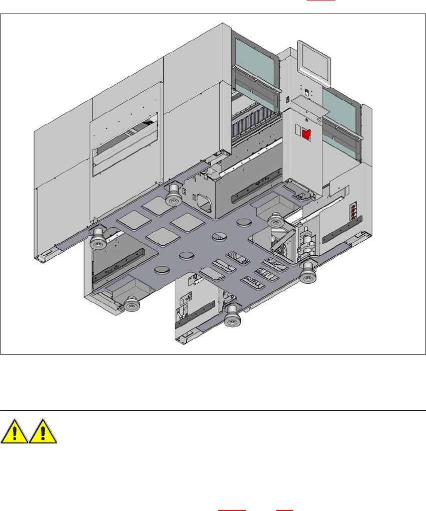
Push the forks of the fork lift under the machine, as shown in fig. 4.3 - 2.
4
Fig. 4.3 - 2 Contact surfaces - forks parallel to the direction of PCB transport (example of SX4)
(1) Contact surfaces for fork lift truck forks
WARNING 4
Please note the following points before you raise the machine in order to avoid irreversible dam-
age to the machine:
– The forks may only be opened to a degree which ensures that they are still within the area of
the two machine feet (contact points see fig. 4.3 - 2
, page 212). The distance between the
machine feet is 776 mm. It is expressly prohibited to increase the fork opening so that the
machine is lifted at the sides of the machine frame. This would lead to the machine frame be-
ing distorted.
User Manual SIPLACE SX4/DX4 4 Setting up and commissioning
From software version SC.706.xx Version 06/2012 EN 4.3 Setting up the machine
213
Make sure that the forks are evenly loaded when you lift the machine. A firm support between
the forks and machine will prevent the machine tilting when it is raised. This will also prevent
a one-sided load on the machine feet, which would deform the fixing of the machine feet. We
recommend that a second person watch the machine as it is raised, and make sure that the
machine does not tip to one side when lifted with the fork-lift.
With the fork-lift, raise the machine approximately 35 cm. This prevents the risk of any injuries
to your feet if the machine feet are unintentionally lowered.
The machine stands on 6 feet.
– 4 outer machine feet (item 1 in fig. 4.3 - 4
, page 214 )
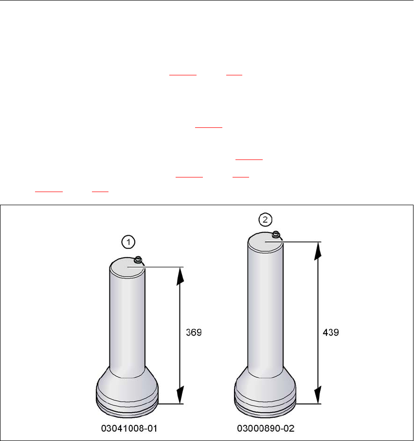
There are two versions of the outer machine feet: 4
– Outer machine feet for the PCB conveyor height 830 mm, length 369 mm,
Item no. 03041008-01 (item 1 in fig. 4.3 - 3
)
– Outer machine feet for the PCB conveyor heights 900,930 and 950 mm, length
439 mm, Item no. 03000890-02 (item 2 in fig. 4.3 - 3
).
– 2 middle machine feet (item 2 in fig. 4.3 - 4
, page 214) with 2 spacers (item 3 and item 4 in
fig. 4.3 - 4
, page 214) for height adjustment, where necessary.
4
Fig. 4.3 - 3 Outer machine feet - two versions (dimensions in millimeters)