00196693-03_UM_SX4DX4_SR706_EN.pdf - 第187页
User Manual SIPLACE SX4/DX4 3 Technical data and assemblies From software version SC.706.xx V ersion 06/2012 EN 3.10 Component trolleys on the SIPLACE SX4 187 3.10.10 Empty tape duct on the component troll ey docking uni…
3 Technical data and assemblies User Manual SIPLACE SX4/DX4
3.10 Component trolleys on the SIPLACE SX4 From software version SC.706.xx Version 06/2012 EN
186
3.10.9 Used tape chute
3
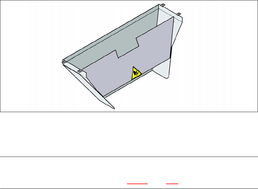
Fig. 3.10 - 10 Used tape chute for the component trolley docking unit
In accordance with the PCB conveyor height, the length of the used tape chute can be set so that
the tape cuttings are directly diverted into the waste tape container of the component trolley.
PLEASE NOTE 3
The used tape chute for the SIPLACE X series can only be installed on the component trolley
docking unit for the SIPLACE X series (see fig. 5.15 - 3, page 292).
User Manual SIPLACE SX4/DX4 3 Technical data and assemblies
From software version SC.706.xx Version 06/2012 EN 3.10 Component trolleys on the SIPLACE SX4
187
3.10.10 Empty tape duct on the component trolley docking unit
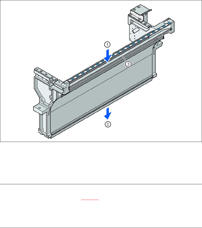
In the standard version, the empty tape duct can guide component tapes with a maximum pocket
height of 12 mm to the pneumatic tape cutter.
3
Fig. 3.10 - 11 Empty tape duct on the SIPLACE X series component trolley docking unit
(1) Inlet slot for the used tapes
(2) Outlet slot for the used tape above the pneumatic tape cutter
(3) Dividing plate for tapes < 12 mm (can be removed for tapes > 12 mm)
PLEASE NOTE
– The separating plate (item 3 in fig. 3.10 - 11
) can be removed for tape pockets higher than 12
mm.
Do not position feeder modules with shallow pockets immediately beside feeder modules with
deep pockets. The used tapes could overlap and build up.
3 Technical data and assemblies User Manual SIPLACE SX4/DX4
3.11 DX table on the SIPLACE DX4 From software version SC.706.xx Version 06/2012 EN
188
3.11 DX table on the SIPLACE DX4
In its default configuration, the SIPLACE DX4 has four DX tables which, if used with 20 SIPLACE
2x8mm X tape feeder modules, can be set up to achieve capacity of up to 40 tracks each for ac-
commodating component types.
Feeder module handling on these DX tables is basically the same as that on the changeover ta-
bles used with the SIPLACE SX4.
3
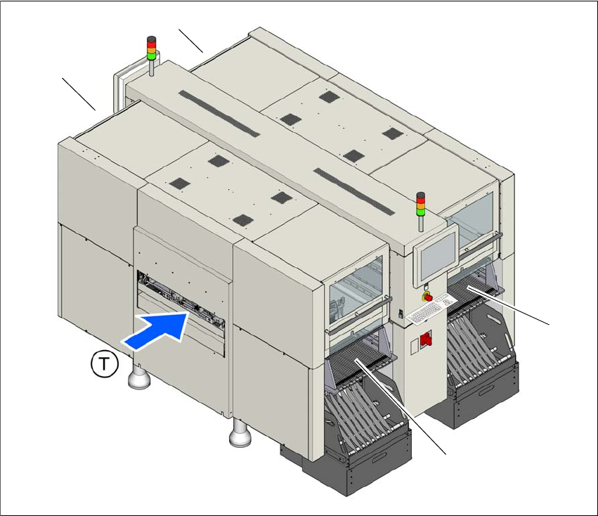
Fig. 3.11 - 1 DX table locations, SIPLACE DX4
(1) Location 1
(2) Location 2
(3) Location 3
(4) Location 4
(T) Direction of PCB transport
(1)
(4)
(2)
(3)