00196693-03_UM_SX4DX4_SR706_EN.pdf - 第144页
3 Technical data and assemblies User Manual SIPLACE SX4/DX4 3.8 Vision system From software version SC.706.xx Version 06/2012 EN 144 3.8.3 S t ationary P&P component cam era, type 33, 55 x 45, digit a l Item no. 0051…
User Manual SIPLACE SX4/DX4 3 Technical data and assemblies
From software version SC.706.xx Version 06/2012 EN 3.8 Vision system
143
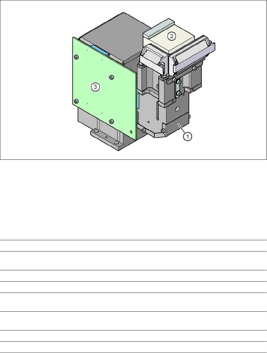
3.8.2 C&P component camera, type 30, 27 x 27, digital
3
Fig. 3.8 - 1 C&P component camera, type 30, 27 x 27, digital
(1) Component camera lens and illumination
(2) Camera amplifier
(3) Illumination control
3.8.2.1 Technical data
3
Component dimensions 0.3 mm x 0.3 mm to 27 mm x 27 mm
Component range 01005 to 27 mm x 27 mm
PLCC, SO, QFP, TSDP, SOT, MELF, CHIP, IC BGA
Min. lead pitch 0.3 mm
Min. lead width 0.15 mm
Min. ball pitch 0.25 mm for components < 18 mm x 18 mm
0.35 mm for components < 18 mm x 18 mm
Min. ball diameter 0.14 mm for components < 18 mm x 18 mm
0.2 mm for components < 18 mm x 18 mm
Field of vision 32 mm x 32 mm
Method of illumination Front-illumination (5 levels, programmable as required)
3 Technical data and assemblies User Manual SIPLACE SX4/DX4
3.8 Vision system From software version SC.706.xx Version 06/2012 EN
144
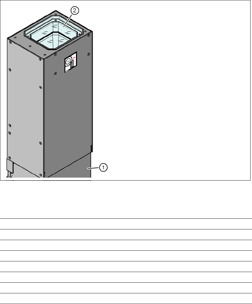
3.8.3 Stationary P&P component camera, type 33, 55 x 45, digital
Item no. 00519902-xx Stationary camera, type 33
3.8.3.1 Structure
3
Fig. 3.8 - 2 Structure for the stationary P&P component camera, type 33, 55 x 45, digital
3.8.3.2 Technical data
3
(1) Camera housing with integral camera
and camera amplifier
(2) Glass plate - illumination and optics un-
derneath
Component dimensions 0.5 mm x 0.5 mm to 55 mm x 45 mm
Component range 0402, MELF, SO, PLCC, QFP, electrolytic capacitors, BGA
Min. lead pitch 0.3 mm
Min. lead width 0.15 mm
Min. ball pitch 0.35 mm
Min. ball diameter 0.2 mm
Field of vision 65 mm x 50 mm
Method of illumination Front-illumination (6 levels, programmable as required)
User Manual SIPLACE SX4/DX4 3 Technical data and assemblies
From software version SC.706.xx Version 06/2012 EN 3.8 Vision system
145
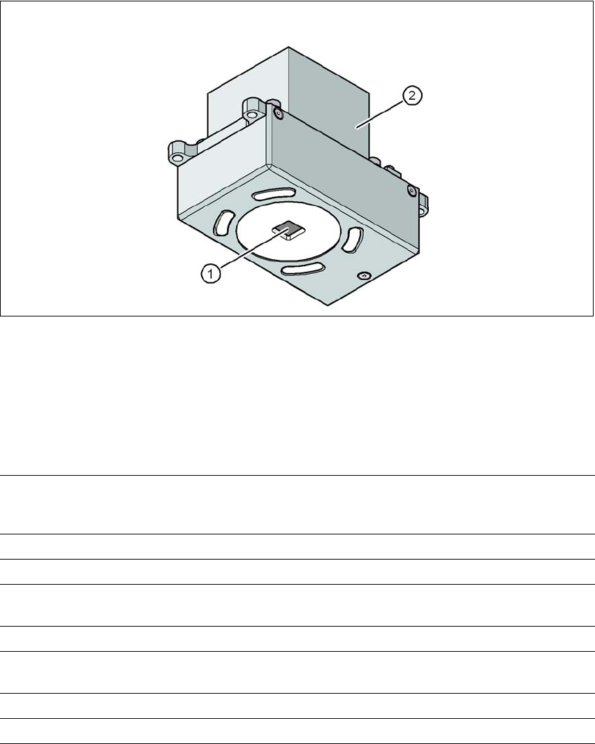
3.8.4 PCB camera, type 34, digital
3.8.4.1 Structure
3
Fig. 3.8 - 3 PCB camera, type 34, digital
(1) PCB camera lens and illumination
(2) Camera amplifier
3.8.4.2 Technical data
3
PCB fiducials Up to 3 (subpanels and multiple panels)
Up to 6 for the Long board option (Optional PCB fiducials are
output by the optimization).
Local fiducials Up to 2 per PCB (may be of different type)
Library memory Up to 255 fiducial types per subpanel
Image analysis Edge detection method (Singular feature) based on grayscale
values
Method of illumination Front-illumination (3 levels, programmable as required)
Detection time per fiducial
/Bad fiducial
20 ms - 200 ms
Field of vision 5.78 mm x 5.78 mm
Distance from the focus plane 28 mm