00196693-03_UM_SX4DX4_SR706_EN.pdf - 第135页
User Manual SIPLACE SX4/DX4 3 Technical data and assemblies From software version SC.706.xx V ersion 06/2012 EN 3.7 PCB conveyor system 135 3.7.3.1 Flexible PCB dual conveyor - convey or lanes and types The right-han d c…
3 Technical data and assemblies User Manual SIPLACE SX4/DX4
3.7 PCB conveyor system From software version SC.706.xx Version 06/2012 EN
134
3.7.3 Structure of the flexible PCB dual conveyor
The flexible dual conveyor has two conveyor tracks that are electrically and mechanically inde-
pendent of one another. The fixed conveyor side is on the right as a standard. The fixed conveyor
side can be either right or left in dual conveyors. Changing the fixed conveyor side from left to right
or vice versa is easily performed in the station software. The PCB dual conveyor can be operated
as a single or dual conveyor, according to your needs.
3
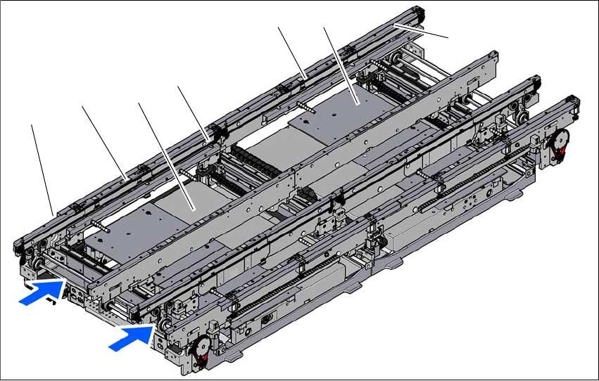
Fig. 3.7 - 2 Structure of the PCB dual conveyor
(1) Input conveyor
(2) Processing conveyor 1
(3) Lifting table 1
(4) Intermediate conveyor
(5) Processing conveyor 2
(6) Lifting table 2
(7) Output conveyor
T1 Conveyor track 1
T2 Conveyor track 2
(7)
(1)
(2)
(3)
(T1)
(T2)
(4)
(5)
(6)
User Manual SIPLACE SX4/DX4 3 Technical data and assemblies
From software version SC.706.xx Version 06/2012 EN 3.7 PCB conveyor system
135
3.7.3.1 Flexible PCB dual conveyor - conveyor lanes and types
The right-hand conveyor lane (viewed in the direction of transport) is known as "conveyor 1" while
the left conveyor lane is termed "conveyor 2" (see fig. 3.7 - 4
, page 136 ).
3.7.3.2 PCB dual conveyor in single conveyor mode
The dual conveyor can be configured online to create a single conveyor. One conveyor lane is
moved together completely and is disabled (see fig. 3.7 - 3
). This gives a conveyor track width of
up to 560 mm.
3
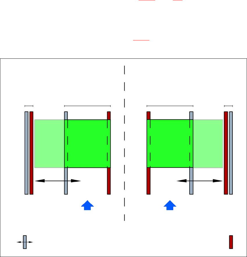
Fig. 3.7 - 3 Flexible dual conveyor in Single conveyor mode
Dual conveyor with widened conveyor track 2
(stationary conveyor side wall on left)
Conveyor track 2
deactivated
Conveyor track 1 Conveyor track 2 Conveyor track 1
deactivated
PCB transport direction PCB transport direction
Stationary conveyor side wall
Dual conveyor with widened conveyor track 1
(stationary conveyor side wall on right)
Movable conveyor side wall
3 Technical data and assemblies User Manual SIPLACE SX4/DX4
3.7 PCB conveyor system From software version SC.706.xx Version 06/2012 EN
136
3.7.3.3 Asynchronous transport mode
In asynchronous mode, only one PCB in a transport track is processed. At the same time, another
PCB in the second transport track is moved into the placement position. This saves the full con-
veying time of one PCB, thus considerably increasing performance, particularly for PCBs with a
short cycle time. Once the machine has received the job data (panel, setup), the PCBs on the
feeding belts are continuously transported to the available processing belt (provided that the pro-
cessing belt is free) throughout the placement operation. The placement process begins as soon
as a board is transported into the processing area. The PCBs are processed one after another.
If the placement sequence is interrupted, the conveyor interface will be disabled and the PCBs
currently on the processing belts will be completed.
The conveyor interface is disabled or enabled simultaneously for both transport tracks.
3
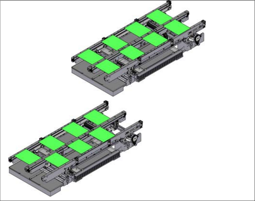
Fig. 3.7 - 4 Transport modes
Synchronous transport mode
Asynchronous transport mode