00196693-03_UM_SX4DX4_SR706_EN.pdf - 第269页
User Manual SIPLACE SX4/DX4 5 Working with the machine From software version SC.706.xx Version 06/2012 EN 5.10 Setting up the feeder modules 269 5.10 Setting up the feeder modules The following chapter shows diagra ms of…
5 Working with the machine User Manual SIPLACE SX4/DX4
5.9 Carrying out a sight check From software version SC.706.xx Version 06/2012 EN
268
5.9.5 Inserting separating plates in the tape container
The separating plate has different edges and can be inserted into the tape container in two
ways. If spindles are used, the recesses for the spindles in the separating plate point upwards
(see item 4 in fig. 5.9 - 3
). If you do not use spindles, the rounded edge of the separating
plate points up (see item 5 in fig. 5.9 - 3
).
Insert the separating plates as shown in fig. 5.9 - 3 and remember that the smallest division
of the tape container is a 2x division. This will help avoid placement errors.
Check that the separating plates engage in the same positions on the three guide rails. Oth-
erwise the separating plate will be offset or bent.
5
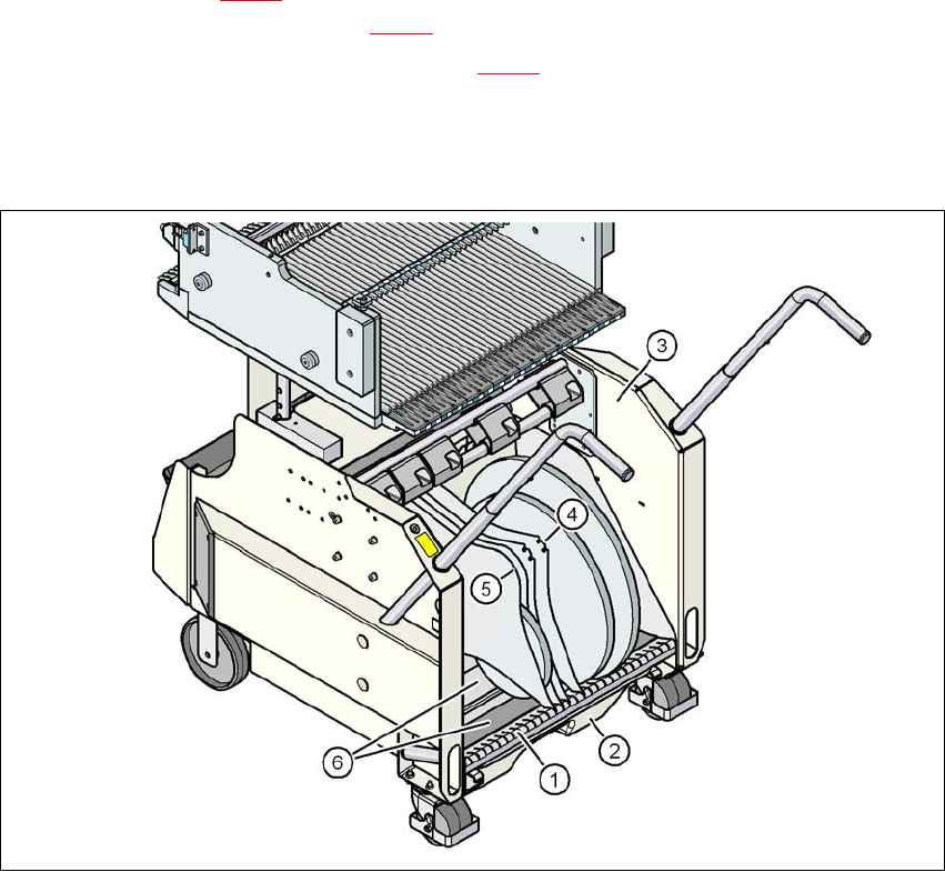
Fig. 5.9 - 3 Separating plates in the tape container
(1) Guide rail for the separating plates
(2) Waste tape container
(3) Tape container
(4) Position of the separating plate if spindles are used
(5) Position of the separating plate if no spindles are used
(6) Sliding support for tape reels
User Manual SIPLACE SX4/DX4 5 Working with the machine
From software version SC.706.xx Version 06/2012 EN 5.10 Setting up the feeder modules
269
5.10 Setting up the feeder modules
The following chapter shows diagrams of the SIPLACE SX4. However, setup of the X feeder mod-
ules on the SIPLACE SX4 changeover tables is basically identical to inspection of the DX tables/
DX changeover tables in the SIPLACE DX4.
5.10.1 Notes on handling feeder modules
Feeder modules are precision devices. You should therefore handle the feeder modules with care.
Avoid bumping feeder modules into obstacles.
Do not drop the feeder modules.
Always use suitable tools for preventive maintenance.
5.10.2 Removing X feeder modules from the changeover table
5
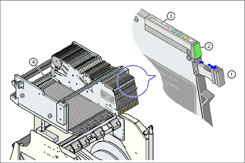
Fig. 5.10 - 1 Removing X feeder modules from the changeover table
(1) Removal handle
(2) Status display
(3) LCD display
(4) Latch for locking the X feeder modules
5
5 Working with the machine User Manual SIPLACE SX4/DX4
5.10 Setting up the feeder modules From software version SC.706.xx Version 06/2012 EN
270
On standby, the status display (item 2 in fig. 5.10 - 1, page 269) lights up green if the X-axis feeder
module is contained in the current setup. If the feeder module is not contained in the current setup,
the status display remains off.
The X feeder module is locked in position in the changeover table by a latch, and cannot be pulled
out. The procedure for removing feeder modules from the changeover table is as follows:
Press the removal handle (item 1 in fig. 5.10 - 1, page 269). The removal handle jumps
out and the status display goes out.
Wait approximately 1 second until the lock (item 4 in fig. 5.10 - 1, page 269) releases the
feeder module.
Use the removal handle to pull the feeder module out of the changeover table. If you wait
longer than 5 seconds, the feeder module will be locked once more. The status display
lights up red and the message (item 3 in fig. 5.10 - 1
, page 269) "Handle --->>" appears
on the LCD display.
Engage the removal handle once more. If the X feeder module is contained in the current
setup, the status display lights up green and the track number and increment are appear
on the LCD display once more.
Press the removal handle again (item 1 in fig. 5.10 - 1, page 269) and now pull the feeder
module out of the changeover table.