00196693-03_UM_SX4DX4_SR706_EN.pdf - 第208页
4 Setting up and commissioning User Manual SIPLACE SX4/DX4 4.3 Setting up the machine From software version SC.706.xx Version 06/2012 EN 208 4.3.2 Lif ting and transporting the m achine with the fork lift truck 4 Fig. 4.…

User Manual SIPLACE SX4/DX4 4 Setting up and commissioning
From software version SC.706.xx Version 06/2012 EN 4.3 Setting up the machine
207
4.3 Setting up the machine
4.3.1 Warning instructions
DANGER 4
Only SIPLACE engineers or qualified people are permitted to set up and commission the machine.
Always follow the applicable accident prevention regulations.
If you still need to perform assembly work to the underside of the machine, take appropriate
measures to secure the machine first. The fork-lift must not be used as the only support.
Make sure that the gantries are positioned over the PCB conveyor area so that you do not
restrict your head movement during assembly, thus excluding the risk of injury.
Two people will be needed to adjust the height of the machine:
– One person to carry out the necessary assembly work and the other person to watch the
watch the raised machine during assembly and ensure that it does not move.
Wear special safety boots to protect your feet.
4 Setting up and commissioning User Manual SIPLACE SX4/DX4
4.3 Setting up the machine From software version SC.706.xx Version 06/2012 EN
208
4.3.2 Lifting and transporting the machine with the fork lift truck
4
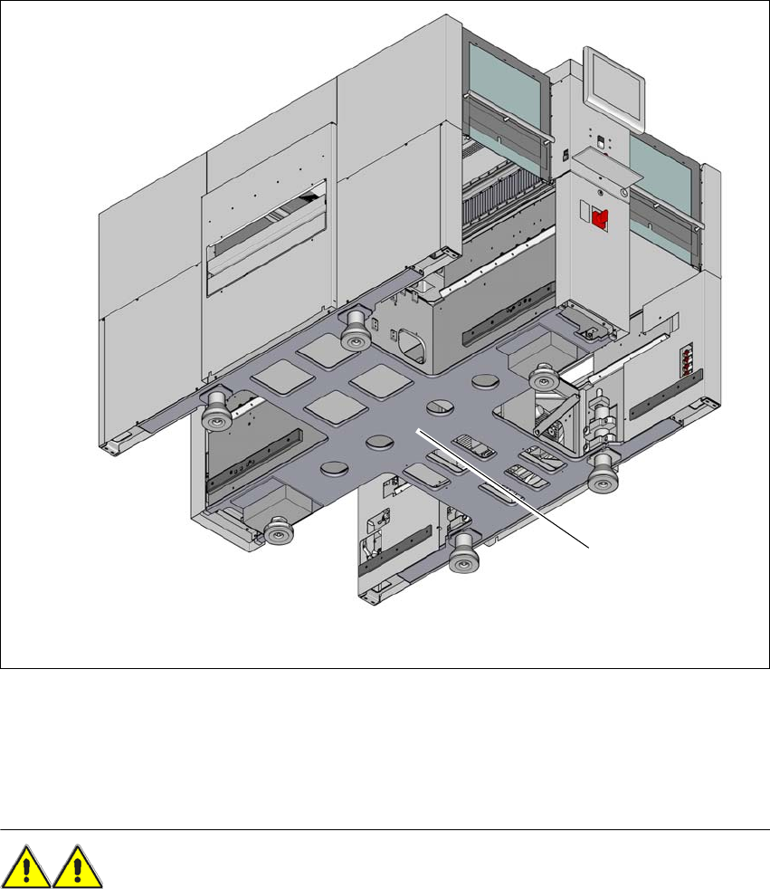
Fig. 4.3 - 1 Contact surface - forks at right angles to the direction of PCB transport (example of SX4)
(1) Contact surface for fork lift truck forks
Position the fork-lift truck at right angles to the PCB conveyor and open the forks until the con-
tact surfaces of the machine lie evenly on the forks.
WARNING 4
Please note the following points before you raise the machine in order to avoid irreversible dam-
age to the machine:
Please note the following points before you raise the machine in order to avoid irreversible dam-
age to the machine:
– The forks must be aligned parallel to the PCB conveyor.
– The forks must be aligned to the center of the machine.
(1)
User Manual SIPLACE SX4/DX4 4 Setting up and commissioning
From software version SC.706.xx Version 06/2012 EN 4.3 Setting up the machine
209
– The forks may only be opened to a degree which ensures that they are still within the contact
area of the machine underside (see fig. 4.1 - 4
, page 197).
– Do not increase the distance between the forks so that the machine is lifted outside this con-
tact surface. This would lead to deformation of the machine frame and/or damage to the ca-
bles and leads.
Make sure that the forks are evenly loaded when you lift the machine. A firm support between
the forks and machine will prevent the machine tilting when it is raised. This will also prevent
a one-sided load on the machine feet, which would deform the fixing of the machine feet. We
recommend that a second person watch the machine as it is raised, and make sure that the
machine does not tip to one side when lifted with the fork-lift.
WARNING 4
When you are transporting the machine, make sure that all the feet are clear of the floor. If they
are not clear, the feet will drag along the floor or bump into obstacles. This could damage the
machine foot fixing in the machine frame.
4.3.3 Fitting attached parts
The machine is delivered with the monitor, operating panel, keyboard and indicator lamp disman-
tled. To fit these components, proceed as follows:
– To fit the indicator lamps see section 4.3.3.2
, page 210
– To fit the operating panel see section 4.3.4, page 210
– To fit the monitors see section 4.3.3.4, page 210
– Hook up the keyboard fixture and connect the keyboard.
– Place the tape container and waste tape container under the DX tables (DX4 only).
4.3.3.1 Checking and setting the protective cover switch
Check the function of the protective cover switch (see 2.5.1 on page 55).
Adjust the protective cover switch if necessary (see service manual).