00196693-03_UM_SX4DX4_SR706_EN.pdf - 第237页
User Manual SIPLACE SX4/DX4 5 Working with the machine From software version SC.706.xx V ersion 06/2012 EN 5.2 Controls and displays 237 5.2 Controls and displays 5.2.1 Overview 5 Fig. 5.2 - 1 Controls and displays (exam…
5 Working with the machine User Manual SIPLACE SX4/DX4
5.1 Personnel profile From software version SC.706.xx Version 06/2012 EN
236
5.1.3 Operator level "Service (Customer)"
5.1.3.1 Tasks
The service personnel's duties include:
– Major preventive maintenance jobs
– Mounting replacement parts
– Editing machine data
– Calibrating the machine
5.1.4 Operator level "Service (SIPLACE)"
5.1.4.1 Tasks
The programmer's jobs are as follows:
– Preparing CAD files
– Creating and calibrating vision data (teaching)
– Writing placement programs
– Implementing a new job
– Data maintenance
– Data backup
User Manual SIPLACE SX4/DX4 5 Working with the machine
From software version SC.706.xx Version 06/2012 EN 5.2 Controls and displays
237
5.2 Controls and displays
5.2.1 Overview
5
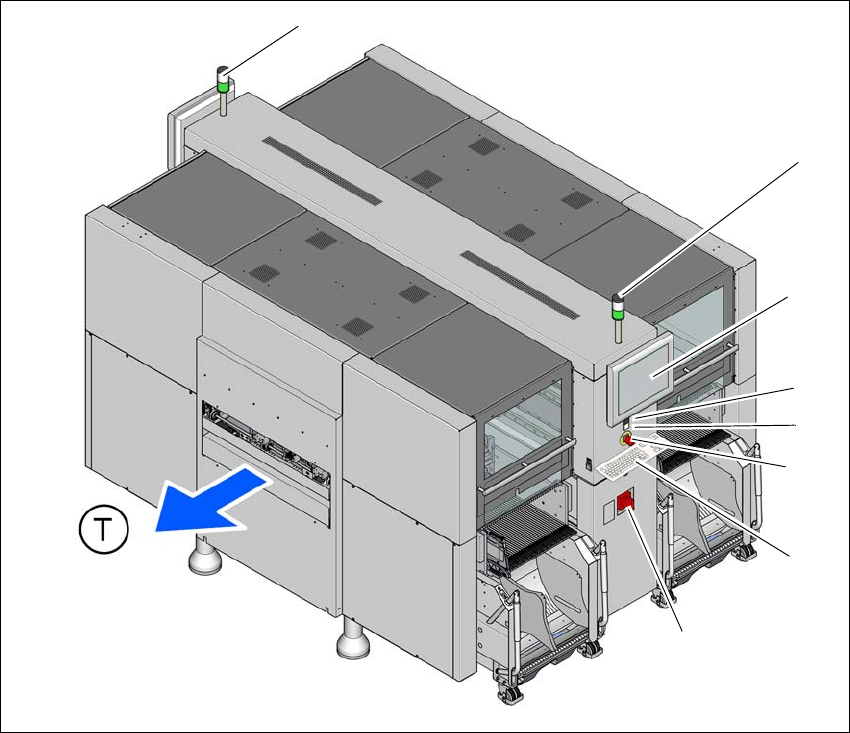
Fig. 5.2 - 1 Controls and displays (example of SX4)
5.2.2 Description
All the controls can be reached by a 1.40 m tall person.
(1) Main power switch (5) Start button (green)
(2) Stop button (black) (6) LCD touchscreen
(3) EMERGENCY STOP button (7) Indicator lamps
(4) Keyboard (T) Direction of PCB transport
(1)
(2)
(3)
(5)
(6)
(7)
(7)
(4)
5 Working with the machine User Manual SIPLACE SX4/DX4
5.2 Controls and displays From software version SC.706.xx Version 06/2012 EN
238
Main power switch 5
The main power switch is used to switch the power supply to the machine on and off.
WARNING
Some parts inside the machine carry potentially lethal voltages - even when switched off at the
main power switch. 5
Stop button 5
This white button is used to stop the machine.
Start button (green) 5
This green button starts the machine after it has been switched on or after faults have been elim-
inated.
EMERGENCY STOP button 5
The EMERGENCY STOP button latches in the ON position when pressed. The power supply to
the gantry axes, the component trolleys, conveyors and used tape cutters is interrupted and the
voltage supplied to the star axes of the placement heads is reduced. Turn the button to release it.
LCD touchscreen 5
There is a flat LCD screen with a touch-sensitive surface (touchscreen) on either side of the place-
ment machine.
Keyboard 5
The keyboard is located beneath the monitor.
CAUTION 5
Risk of collision on the monitor with keyboard
When working on the component trolley, there is risk that you could collide with the monitor and
keyboard.
– Turn the monitor and keyboard away to the side.
– Make sure that you are not under the monitor and keyboard with your head.
5