00196693-03_UM_SX4DX4_SR706_EN.pdf - 第199页
User Manual SIPLACE SX4/DX4 4 Setting up and commissioning From software version SC.706.xx V ersion 06/2012 EN 4.2 Infrastructure at the installation location 199 4.2.2.2 Compressed air connection on the machine 4 Fig. 4…
4 Setting up and commissioning User Manual SIPLACE SX4/DX4
4.2 Infrastructure at the installation location From software version SC.706.xx Version 06/2012 EN
198
4.2 Infrastructure at the installation location
4.2.1 Recommendations for the foundation quality
The foundation on which the machine is installed must be firm and level, as dynamic forces could
cause vibrations when the machine is operated. The degree of vibration depends on the construc-
tion of the foundation. The following are suitable provided that the floor loading parameters, etc.,
are not exceeded:
– Reinforced concrete ceiling constructions, e.g. ceilings in production halls
– Reinforced concrete floor slabs, e.g. concrete floors in production halls without a basement
– Rooms with double floors, provided that a stable foundation is included in the space between
them. The same setup conditions apply to this intermediate foundation, which can be made
from steel girders or concrete.
4.2.1.1 Maximum ground levelness
The floor underneath the machine may not exceed an incline of 0.63%. This corresponds to an
incline of 5 mm over a distance of 800 mm (e.g. the width of a changeover table).
4.2.1.2 Machine weight and floor loading
the machine weight and floor loading values can be found in section 3.3.1, page 103.
4
4.2.2 Compressed air supply
4.2.2.1 Checking the compressed air supply
Check whether the compressed air supply complies with the prescribed machine specifications
(see table in section 3.2
, page 101).
PLEASE NOTE: 4
The documentation "Network Configuration (Electrics and Compressed Air) for SMD Machines at
Customer Site", Item No. 00191409-xx includes the measures required to achieve the specifica-
tions needed.
Record the compressed air characteristics at the installation location.
WARNING
NEVER detach compressed air lines while they are still pressurized. Risk of injury. 4
User Manual SIPLACE SX4/DX4 4 Setting up and commissioning
From software version SC.706.xx Version 06/2012 EN 4.2 Infrastructure at the installation location
199
4.2.2.2 Compressed air connection on the machine
4
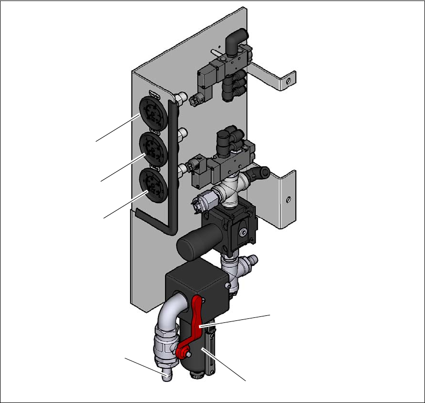
Fig. 4.2 - 1 Compressed air unit on the machine
Legend for fig.4.2 - 1
(1) Manometer for inlet pressure
Target pressure: 0.5 - 1.0 MPa, 5 - 10 bar (display range: 0 - 1.0 MPa, 0 - 10 bar)
(2) Manometer for supply pressure of gantries 1 to 4
Target pressure: 0.46 ± 0.01 MPa, 4.6 ± 0.1 bar (display range 0 - 0.6 MPa, 0 - 6 bar)
(3) Manometer for the machine component supply pressure
Target pressure: 0.5 ± 0.025 MPa, 5 ± 0.25 bar (display range 0 - 0.6 MPa, 0 - 6 bar)
(4) Stop valve in the "OPEN" position
(5) Compressed air filter
(6) Compressed air connection
(6)
(1)
(2)
(3)
(5)
(4)
4 Setting up and commissioning User Manual SIPLACE SX4/DX4
4.2 Infrastructure at the installation location From software version SC.706.xx Version 06/2012 EN
200
4.2.3 Main power supply
4
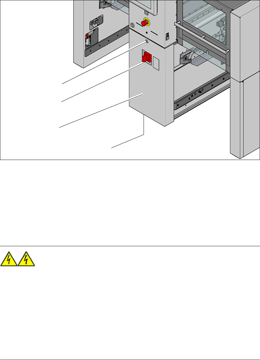
Fig. 4.2 - 2 Position of the power supply on the machine (example of SX4)
(1) Lock
(2) Main power switch secured to prevent switching on again
(3) Power supply unit (behind the cover)
(4) Mains connection cable
4.2.3.1 Danger notes
WARNING
The machine is supplied with 3 x 200 V~, 3 x 208 V~, 3 x 220 V~, 3 x 230 V~, 3 x 380 V~,
3x400V~ or 3x415V~ ± 5%, 50/60Hz mains voltage. This means that some parts of the sys-
tem carry potentially lethal voltages - even when switched off at the main power switch. Incorrect
handling of the machine can therefore result in death or severe injury or considerable damage to
equipment. 4
Always follow the applicable accident prevention and DIN regulations (particularly EN 60204,
part 1 or IEC 60204, part 1) and the applicable regulations in your own country.
Only trained and qualified personnel may remove the cover over the power supply unit and
connect the machine to the power supply.
(1)
(2)
(3)
(4)