00196693-03_UM_SX4DX4_SR706_EN.pdf - 第297页
User Manual SIPLACE SX4/DX4 6 Station extensions From software version SC.706.xx V ersion 06/2012 EN 6.1 Nozzle changer 297 6 Fig. 6.1 - 2 Position of nozzle changer for the SIPLACE SpeedStar - configuration example (SX4…

6 Station extensions User Manual SIPLACE SX4/DX4
6.1 Nozzle changer From software version SC.706.xx Version 06/2012 EN
296
6.1.1.1 Description
This nozzle changer can accommodate 6 magazines, each with 12 nozzle garages. The maga-
zines are seated on a common support. They are centered with two parallel pins and fixed in place
with 4 push buttons. The exact position is determined with two fiducials on each magazine. The
correct seat of the magazines on the basic nozzle changer body is monitored by microswitches,
to prevent a collision of the placement head with any magazines projecting upwards. All magazine
locations must be filled since the safety circuit stops the machine in response to missing maga-
zines or magazines that are not seated correctly. At the installed nozzle station, components can
be blown off the nozzles of the SpeedStar and nozzles stripped off and rejected.
PLEASE NOTE 6
The nozzle changer can only be used in conjunction with the SpeedStar.
6.1.1.2 Technical data
6
6.1.1.3 Position of nozzle changer for the SIPLACE SpeedStar
Locations 1, 2, 3 and 4 can each accommodate one nozzle changer for the SpeedStar (item 1 in
fig. 6.1 - 2
, page 297).
This gives the following nozzle changer configurations for the placement machine:
6
Nozzle changer for the SIPLACE SpeedStar
Dimensions (length x width x height) 449 mm x 94.5 mm x 79 mm
Number of nozzle holders 72
Number of nozzle magazines 6
Nozzle types 10xx, 11xx and 12xx
Nozzle changeover time approx. 2s per nozzle
Compressed air connection 0.48 MPa (4.8 bar)
Location
Number of nozzle
magazines
Number of spare nozzle
magazines
Number of nozzle
holders
16 - 72
2 4 2 48 (+ 24 spare)
36 - 72
4 4 2 48 (+ 24 spare)
User Manual SIPLACE SX4/DX4 6 Station extensions
From software version SC.706.xx Version 06/2012 EN 6.1 Nozzle changer
297
6
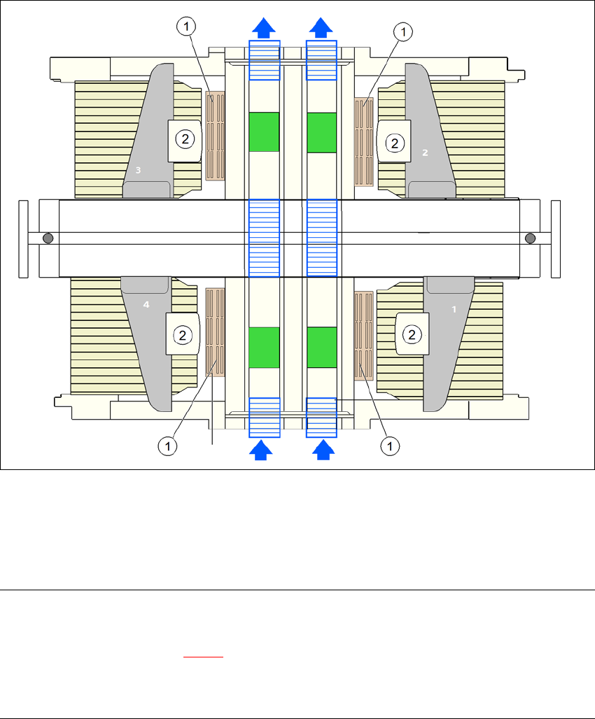
Fig. 6.1 - 2 Position of nozzle changer for the SIPLACE SpeedStar - configuration example (SX4)
6
PLEASE NOTE: 6
– The placement heads at locations 2 and 4 are not able to access the two innermost nozzle
magazines (item 2 in fig. 6.1 - 2
).
– All magazine locations must be filled since the safety circuit stops the machine in response
to missing magazines or magazines that are not seated correctly.
6
(1) Nozzle changer
(2) SIPLACE SpeedStar
6 Station extensions User Manual SIPLACE SX4/DX4
6.1 Nozzle changer From software version SC.706.xx Version 06/2012 EN
298
6.1.1.4 Assembly
The nozzle changers are fixed to the component trolley docking unit or to the DX table.
6
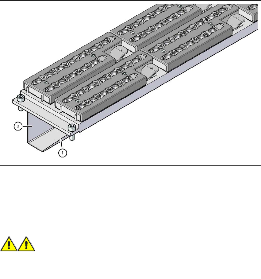
Fig. 6.1 - 3 Assembly position
(1) Sloping side points towards the component trolley docking unit/DX table
(2) Vertical side points towards the PCB conveyor
Align the nozzle changer so that the sloping side points towards the component trolley dock-
ing unit/DX table.
WARNING 6
– Only install the corresponding nozzle changers for each placement head. There is a risk of
head crashes with mixed configurations.