00196693-03_UM_SX4DX4_SR706_EN.pdf - 第246页
5 Working with the machine User Manual SIPLACE SX4/DX4 5.5 The user interface From software version SC.706.xx Version 06/2012 EN 246 5.5 The user interface The user inte rface is divided into th e following areas. The us…
User Manual SIPLACE SX4/DX4 5 Working with the machine
From software version SC.706.xx Version 06/2012 EN 5.4 Switching off the SIPLACE line
245
5.4 Switching off the SIPLACE line
CAUTION
Before you switch off the line, observe the following procedures. 5
5.4.1 Switching off the stations
To switch off the stations, proceed as follows:
End all placement procedures, so that there are no more boards in the machine.
Check whether the Z axes of all placement heads are in their uppermost end positions.
Check whether there are still components on the placement heads and remove these.
Close the station computer software in the view
Settings --> Machine Settings --> Shut Down Machine...
Once the computer has been shut down, switch off the station at the main switch.
5.4.2 Exiting SIPLACE Pro (Windows)
In the SIPLACE Pro menu, select Object --> Close.
Close all other programs on the computer.
Select Shut down from the Windows Start menu.
5 Working with the machine User Manual SIPLACE SX4/DX4
5.5 The user interface From software version SC.706.xx Version 06/2012 EN
246
5.5 The user interface
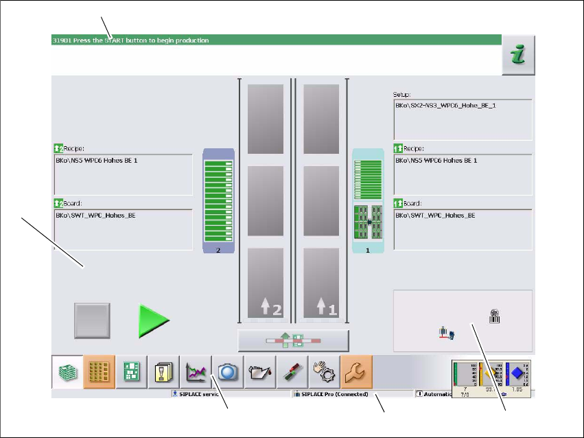
The user interface is divided into the following areas.
The user interface with the "Production" view for the SX machine is shown as an example.
Fig. 5.5 - 1 User interface components in the "Production" (example of SIPLACE SX shown) view
Legend
(1) Status field (status and error display)
(2) Processing area / display area
(3) Toolbar
(4) Information line
(5) View of changed configurations and additional options e.g. barcode mode
(1)
(2)
(3)
(4)
(5)
User Manual SIPLACE SX4/DX4 5 Working with the machine
From software version SC.706.xx Version 06/2012 EN 5.5 The user interface
247
5.5.1 Status field
The status field shows the current machine status, the error which occurred most recently and the
action to be performed.
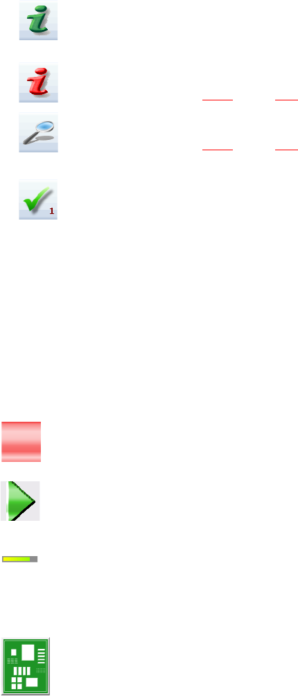
The right-hand side of the status field shows the status with the following icons:
(Green) Starts the context-sensitive Online Help function for the current view. All operating con-
trols for the current view are explained
(Red) Starts the help system, showing the possible causes of the current errors and suitable so-
lutions (see section 5.6.1
, page 254).
Opens a dialog box in which the error source, error message text and the error date with time are
shown (see section 5.6.1
, page 254). The help function for the current error can also be opened
from here.
Deletes the error currently shown from the status field.
5.5.2 Display and processing area
This area shows the buttons for setting/deleting functions, general information about the board,
setup, recipes and other information.
Animated and color-coded items helps explain processes or states (e.g. editing, empty location
etc.).
The "Production" (basic view) view indicates certain operating states (editing, error etc.).
Stop processing. This stops the current processing run.
Continue processing. This starts or continues board placement.
Progress bar
The placement progress is shown for each board on the progress bar.
Boards being processed
The board is taken up by the system and placed. The PCB icon will be shown as a dark green
button.