00196693-03_UM_SX4DX4_SR706_EN.pdf - 第97页
User Manual SIPLACE SX4/DX4 3 Technical data and assemblies From software version SC.706.xx Version 06/2012 EN 3.1 Performance data 97 3.1.2.2 SIPLACE DX4 3 Component range a C&P20 01005 to max. 6 mm x 6 mm Component…
3 Technical data and assemblies User Manual SIPLACE SX4/DX4
3.1 Performance data From software version SC.706.xx Version 06/2012 EN
96
3.1.2 Placement data
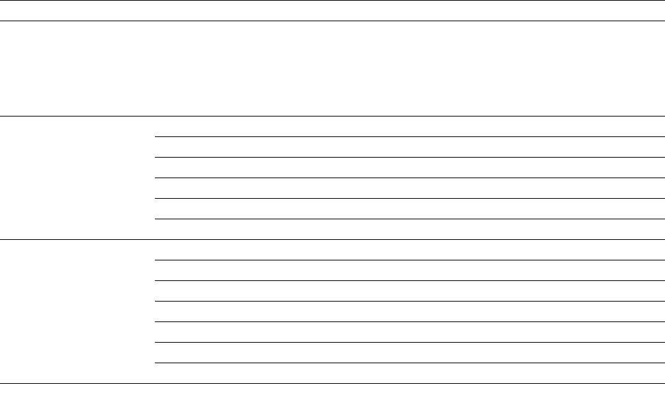
3.1.2.1 SIPLACE SX4
3
Component range
a
01005 to max. 200 mm x 110 mm
Component height C&P20
CPP
b
CPP
c
TH
4 mm
6 mm
8.5 mm to 11.5 mm
25 mm (greater height on request)
X/Y accuracy
d
C&P20 ± 41 μm (3), ± 55 μm (4) Component camera, type 23 (6 x 6)
C&P20 ± 41 μm (3), ± 55 μm (4) Component camera, type 41 (6 x 6)
CPP ± 41 μm (3), ± 55 μm (4) Component camera, type 30 (27 x 27)
CPP ± 34 μm (3), ± 45 μm (4) Component camera, type 33 (55 x 45)
TH ± 26 μm (3), ± 35 μm (4) Component camera, type 33 (55 x 45)
TH ± 22 μm (3), ± 30 μm (4) Component camera, type 25 (16 x 16)
Angular accuracy C&P20 ± 0.5° (3), ± 0.7° (4) Component camera, type 23 (6 x 6)
C&P20 ± 0.5° (3), ± 0.7° (4) Component camera, type 41 (6 x 6)
CPP
e
± 0.4° (3), ± 0.5° (4) Component camera, type 30 (27 x 27)
CPP
f
± 0.5° (3), ± 0.7° (4) Component camera, type 30 (27 x 27)
CPP ± 0.2° (3), ± 0.3° (4) Component camera, type 33 (55 x 45)
TH ± 0.05° (3), ± 0.07° (4) Component camera, type 33 (55 x 45)
TH ± 0.05° (3), ± 0.07° (4) Component camera, type 25 (16 x 16)
a) Please note that the component range that can be placed is also affected by the pad geometry, the customer-specific stan-
dards, the component packaging tolerances and the component tolerances.
b) CPP head: in low installation position (stationary component camera not possible).
c) CPP head: in high installation position
d) The accuracy value, measured using the vendor-neutral IPC standard.
e) Component dimensions between 6 mm x 6 mm and 27 mm x 27 mm.
f) Component dimensions smaller than 6 mm x 6 mm.

User Manual SIPLACE SX4/DX4 3 Technical data and assemblies
From software version SC.706.xx Version 06/2012 EN 3.1 Performance data
97
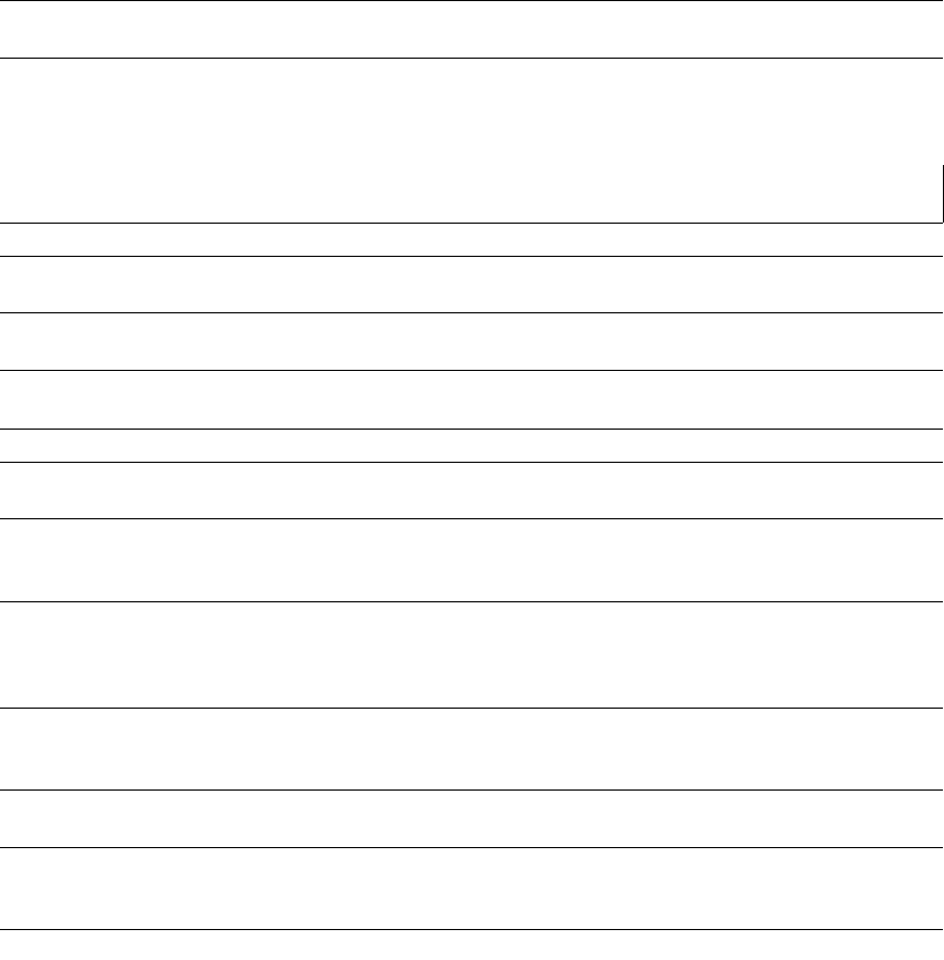
3.1.2.2 SIPLACE DX4
3
Component range
a
C&P20 01005 to max. 6 mm x 6 mm
Component height C&P20 4 mm
X/Y accuracy
b
C&P20 ± 41 μm (3), ± 55 μm (4) Component camera, type 23 (6 x 6)
Angular accuracy C&P20 ± 0.5° (3), ± 0.7° (4) Component camera, type 23 (6 x 6)
a) Please note that the component range that can be placed is also affected by the pad geometry, the customer-specific stan-
dards, the component packaging tolerances and the component tolerances.
b) The accuracy value, measured using the vendor-neutral IPC standard.
3 Technical data and assemblies User Manual SIPLACE SX4/DX4
3.1 Performance data From software version SC.706.xx Version 06/2012 EN
98
3.1.3 Board conveyor data
3.1.3.1 SIPLACE SX4
3
Flexible dual con-
veyor
Dual conveyor in sin-
gle conveyor mode
Quad lane conveyor
Board dimensions
(length x width
a
)
Standard:
a) When using board widths > 450 mm, make sure that the peripheral modules can also process these board
widths.
50 mm x 50 mm to
285mm x 325mm
50 mm x 50 mm to
285 mm x 560 mm
50 mm x 50 mm to
285 mm x 150 mm
Option: “Long Board 50 mm x 50 mm to
450mm x 325mm
50 mm x 50 mm to
450 mm x 560 mm
--
Option: “Long Board 550 -- -- --
Stationary conveyor side Right, left or outer
Automatic electrical width
adjustment
Yes
PCB thickness
Standard: 0.3 mm to 4.5 mm
PCB warpage See page 140
PCB weight
b
standard
b) The board weight value refers to the weight of the board plus the weight of the components.
max. 1.0 kg max. 2.0 kg max. 0.5 kg
Clearance on PCB under-
side
Standard stopper: Up to 25 mm
PCB conveyor height
Option:
Standard:
SMEMA option:
900 mm
930 mm
950 mm
Type of interface:
Standard:
Option:
SMEMA
Siemens
component-free PCB han-
dling edge
3 mm
PCB changeover time
Single conveyor
Dual conveyor
c
c) 0 seconds in asynchronous mode, otherwise 1.5 seconds.
< 1.5 seconds
0 seconds