00196693-03_UM_SX4DX4_SR706_EN.pdf - 第143页
User Manual SIPLACE SX4/DX4 3 Technical data and assemblies From software version SC.706 .xx V ersion 06/2012 EN 3.8 Vision system 143 3.8.2 C&P component camera, type 30, 27 x 27, digital 3 Fig. 3.8 - 1 C&P comp…

3 Technical data and assemblies User Manual SIPLACE SX4/DX4
3.8 Vision system From software version SC.706.xx Version 06/2012 EN
142
3.8 Vision system
3.8.1 Structure
A component camera is integrated at each Collect&Place head (see fig. 3.5 - 2 page 112 and fig.
3.5 - 4
page 117). The component camera, stationary, P&P (type 33) 55 x 45, digital, for the Mul-
tiStar and the TwinStar is fixed to the machine frame.
The component vision module is used to determine:
– the precise position of the components at the nozzle and
– the geometry of the package form.
The PCB vision module uses fiducials on the PCBs to determine:
– the position of the PCB,
– its rotation angle
– and the PCB skew.
The PCB cameras are fixed to the bottom of the gantries. They use fiducials on the feeder mod-
ules to determine the exact pick-up position of components, which is particularly important for
small components.
WARNING
RISK OF HEAD CRASH 3
When changing the placement head from TwinStar to SpeedStar, the stationary component cam-
eras of type 33, 55 x 45, digital, and type 25, 16 x 16, digital (FC camera) need to be dismantled
from the TwinStar, otherwise the SpeedStar will collide with the camera housing.
When changing the placement head from TwinStar to MultiStar, the stationary component cam-
era, type 33, 55 x 45, digital, is fitted in the bottom position.
User Manual SIPLACE SX4/DX4 3 Technical data and assemblies
From software version SC.706.xx Version 06/2012 EN 3.8 Vision system
143
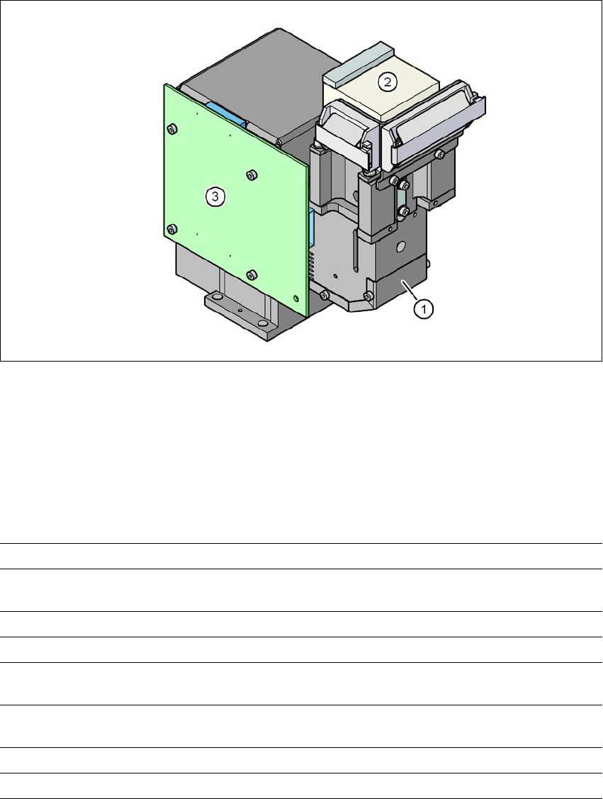
3.8.2 C&P component camera, type 30, 27 x 27, digital
3
Fig. 3.8 - 1 C&P component camera, type 30, 27 x 27, digital
(1) Component camera lens and illumination
(2) Camera amplifier
(3) Illumination control
3.8.2.1 Technical data
3
Component dimensions 0.3 mm x 0.3 mm to 27 mm x 27 mm
Component range 01005 to 27 mm x 27 mm
PLCC, SO, QFP, TSDP, SOT, MELF, CHIP, IC BGA
Min. lead pitch 0.3 mm
Min. lead width 0.15 mm
Min. ball pitch 0.25 mm for components < 18 mm x 18 mm
0.35 mm for components < 18 mm x 18 mm
Min. ball diameter 0.14 mm for components < 18 mm x 18 mm
0.2 mm for components < 18 mm x 18 mm
Field of vision 32 mm x 32 mm
Method of illumination Front-illumination (5 levels, programmable as required)
3 Technical data and assemblies User Manual SIPLACE SX4/DX4
3.8 Vision system From software version SC.706.xx Version 06/2012 EN
144
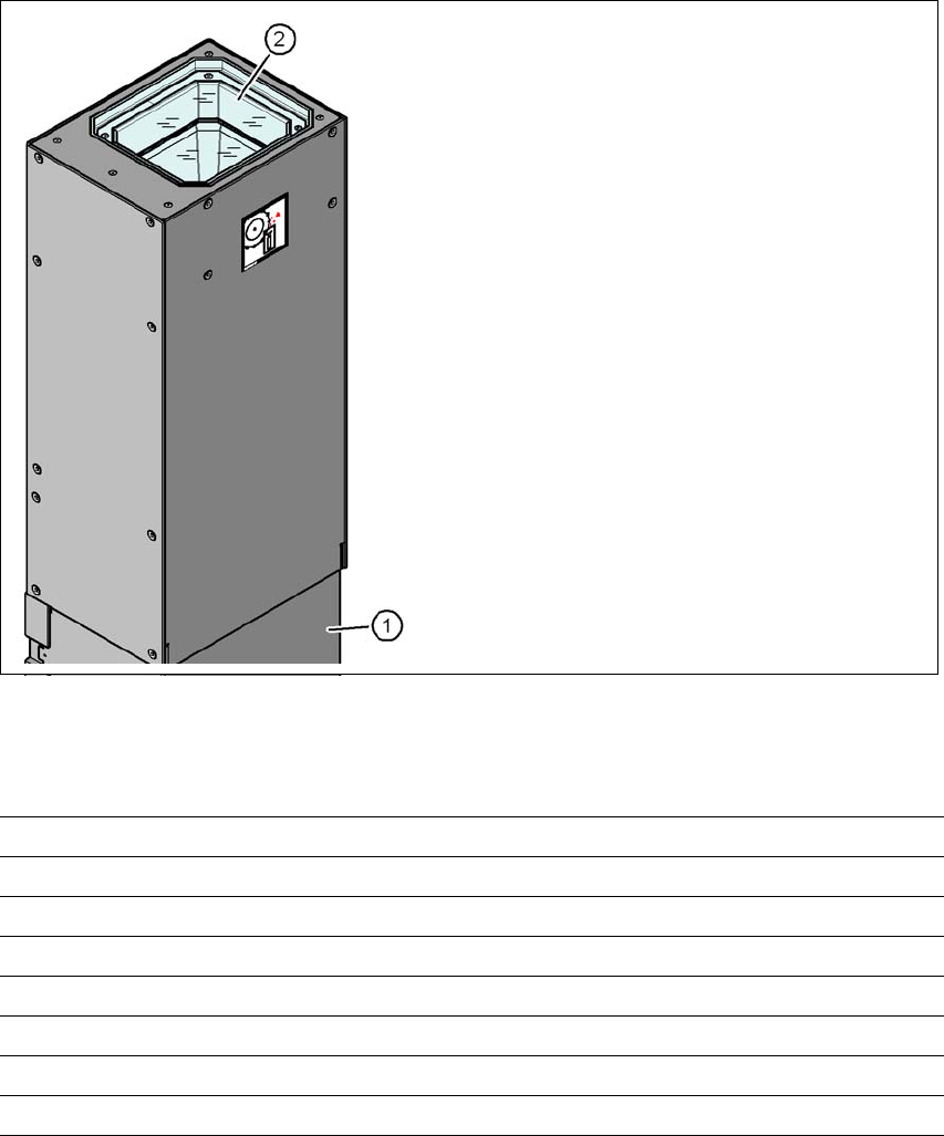
3.8.3 Stationary P&P component camera, type 33, 55 x 45, digital
Item no. 00519902-xx Stationary camera, type 33
3.8.3.1 Structure
3
Fig. 3.8 - 2 Structure for the stationary P&P component camera, type 33, 55 x 45, digital
3.8.3.2 Technical data
3
(1) Camera housing with integral camera
and camera amplifier
(2) Glass plate - illumination and optics un-
derneath
Component dimensions 0.5 mm x 0.5 mm to 55 mm x 45 mm
Component range 0402, MELF, SO, PLCC, QFP, electrolytic capacitors, BGA
Min. lead pitch 0.3 mm
Min. lead width 0.15 mm
Min. ball pitch 0.35 mm
Min. ball diameter 0.2 mm
Field of vision 65 mm x 50 mm
Method of illumination Front-illumination (6 levels, programmable as required)