00196693-03_UM_SX4DX4_SR706_EN.pdf - 第332页
6 Station extensions User Manual SIPLACE SX4/DX4 6.8 Component camera for the TwinStar, FC camera From software version SC.706.xx Version 06/2012 EN 332 6.8 Component camera for the T winSt ar , FC camera 6.8.1 S t ation…

User Manual SIPLACE SX4/DX4 6 Station extensions
From software version SC.706.xx Version 06/2012 EN 6.7 SIPLACE High-Force Head
331
6.7 SIPLACE High-Force Head
Item no. 00119736-xx High-Force Head
This item number only applies when ordering a new placement machine with a high force
head instead of a standard TwinStar. 6
6.7.1 Description
The SIPLACE high force head is an advanced development of the standard TwinStar. It can pro-
cess the same component range and also offers the possibility of achieving set-down forces up to
30 N. The SIPLACE high force head can use all the same nozzles and grippers as the standard
TwinStar.
6.7.2 Technical data
6
Al other technical data are identical for the TwinStar and high force head (see section 3.5.3.2,
page 127
).
Programmable set-down force 2.0 N to 10 N ± 10 %
greater than 10 N up to 30 N ± 15 %
6 Station extensions User Manual SIPLACE SX4/DX4
6.8 Component camera for the TwinStar, FC camera From software version SC.706.xx Version 06/2012 EN
332
6.8 Component camera for the TwinStar, FC camera
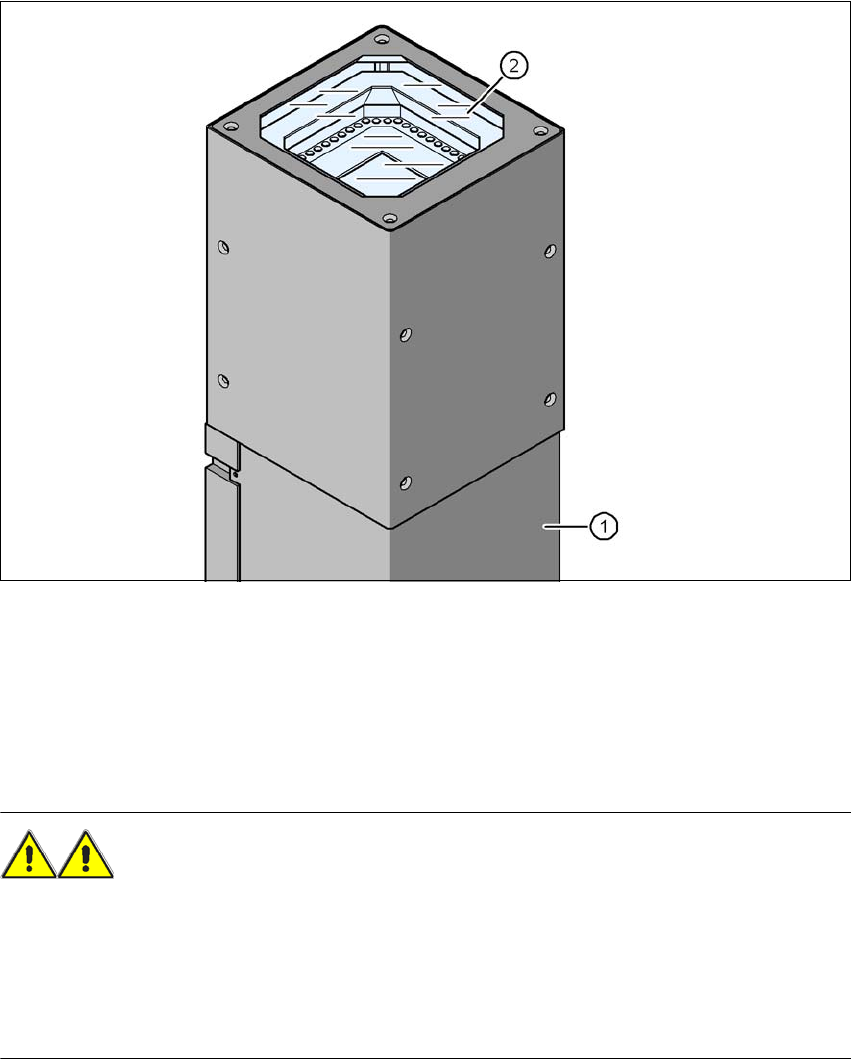
6.8.1 Stationary P&P component camera (type 25) 16 x 16, digital (FC camera)
Item no. 00119718-xx Stationary component camera 16x16 digital, type 25
6
Fig. 6.8 - 1 Stationary P&P component camera (type 25) 16 x 16, digital (FC camera)
(1) Camera housing with integral camera and camera amplifier
(2) Glass plate - over the illumination and lens levels
6.8.2 Safety instructions
WARNING 6
When changing the placement head from TwinStar to SpeedStar, the stationary component cam-
eras of type 33, 55 x 45, digital, and type 25, 16 x 16, digital (FC camera) need to be dismantled
from the TwinStar, otherwise the SpeedStar will collide with the camera housing.
When changing the placement head from TwinStar to MultiStar, the stationary component cam-
era, type 33, 55 x 45, digital, is fitted in the bottom position.

User Manual SIPLACE SX4/DX4 6 Station extensions
From software version SC.706.xx Version 06/2012 EN 6.8 Component camera for the TwinStar, FC camera
333
6.8.3 Technical data
6
6
6
6
6.8.4 Position
The position of the stationary component cameras and the associated configurations are de-
scribed
in section 3.8.2
, from page 143.
Component dimensions 0.2 mm x 0.2 mm up to 16 mm x 16 mm for single component
measurement
Component range 0402 to SO, PLCC, QFP, sockets, plugs, BGA, special components,
bare dies, flip-chips, shields
Min. lead pitch 0.25 mm
Min. lead width 0.1 mm
Min. ball pitch 0.14 mm
Min. ball diameter 0.08 mm
Field of vision 19.4 mm x 19.4 mm
Method of illumination Front-illumination (6 levels, programmable as required)