00196693-03_UM_SX4DX4_SR706_EN.pdf - 第278页
5 Working with the machine User Manual SIPLACE SX4/DX4 5.10 Setting up the feeder modules From software version SC.706.xx Version 06/2012 EN 278 5.10.4.4 T ape support for 8 mm X t ape feeder module 5 Fig. 5.10 - 8 8 mm …
User Manual SIPLACE SX4/DX4 5 Working with the machine
From software version SC.706.xx Version 06/2012 EN 5.10 Setting up the feeder modules
277
Push the lever (item 5 in fig. 5.10 - 5, page 276) forward in order to raise the pickup window
(item 2 in fig. 5.10 - 5
, page 276) into the first latching position.
Pull the cover foil at the side of the pick-up window forward and out underneath the pick-up
window.
Fold the cover foil back until it lies against the pull-off edge (item 3 in fig. 5.10 - 5, page 276).
PLEASE NOTE 5
Do not lower the pick-up window until the cover foil is lying against the pull-off edge.
Push the lever (item 5 in fig. 5.10 - 5, page 276) back to lower the pickup window.
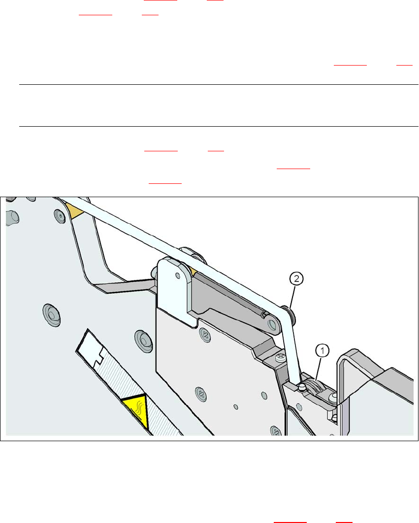
Guide the cover foil over the cover foil rocker (item 2 in fig. 5.10 - 7) until it reaches the foil
packing wheels (item 1 in fig. 5.10 - 7
).
5
Fig. 5.10 - 7 Guiding the cover foil to the foil packing wheels
(1) Cover foil packing wheels
(2) Cover foil
5
On the operator panel, press the FOIL button (item 3 in fig. 5.10 - 6, page 276) until the cover
foil is tensioned. The cover foil rocker points down and stops the drive motor.
Cut the component tape flush with the front end of the feeder module.
5 Working with the machine User Manual SIPLACE SX4/DX4
5.10 Setting up the feeder modules From software version SC.706.xx Version 06/2012 EN
278
5.10.4.4 Tape support for 8 mm X tape feeder module
5
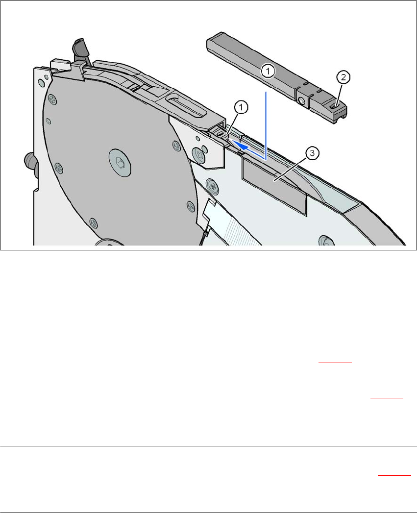
Fig. 5.10 - 8 8 mm X feeder module - tape support and splice sensor
(1) Tape support, removable
(2) Oval opening in the tape support
(3) Splice sensor installation location
The 8 mm X feeder module is equipped with a tape support (item 1 in fig. 5.10 - 8
). It can easily
be removed if necessary.
Insert the tang of a watchmaker's screwdriver into the oval opening (item 2 in fig. 5.10 - 8) in
the tape support and pull the tape support out against the direction of travel of the tape.
When you insert the tape support, make sure that it engages in its desired position.
PLEASE NOTE 5
For all components size 0402 and smaller, always insert the tape support (item 1 in fig. 5.10 - 8
)
into the 8 mm X feeder module. This will give you a constant Z pick up height and will minimize
the time needed to correct the pick up heights.

User Manual SIPLACE SX4/DX4 5 Working with the machine
From software version SC.706.xx Version 06/2012 EN 5.10 Setting up the feeder modules
279
5.10.4.5 Splice sensors for X tape feeder modules
Splice sensors can be retrofitted to the X tape feeder modules. There are two versions of the sen-
sor:
Splice sensor for 8 mm and 12 mm X tape feeder modules
Splice sensor for 16 mm to 88 mm X tape feeder modules 5
The splice sensor is installed at the position indicated by item 3 in fig. 5.10 - 8
, page 278.
Tape feeder modules with a splice sensor already installed can also be supplied (see section
3.9.2
, from page 152).
5.10.5 Placing components on the 2x8 mm tape feeder module
The operation and configuration of 2x8 mm feeder modules is described in the "Tape Feeder Mod-
ule 2x8 mm X / Smart Feeder 12 mm X /16 mm X Job Guide".
Item number for German 00196664-xx
Item number for English 00196665-xx
5.10.6 Configuring components on the SIPLACE smart feeder
The operation and configuration of the SIPLACE smart feeder is described in the "Tape Feeder
Module 2x8 mm X / Smart Feeder 12 mm X /16 mm X Job Guide".
Item number for German 00196664-xx
Item number for English 00196665-xx