00196693-03_UM_SX4DX4_SR706_EN.pdf - 第63页
User Manual SIPLACE SX4/DX4 2 Operational safety From software version SC.706.xx Version 06/2012 EN 2.6 Ad ditional safety instructions for the SX4 machine 63 2.6.4 Safety instructions for em ptying the waste tape cont a…
2 Operational safety User Manual SIPLACE SX4/DX4
2.6 Additional safety instructions for the SX4 machine From software version SC.706.xx Version 06/2012 EN
62
2.6.2 Safety instructions for the component cameras of the TwinStar during place-
ment head change
WARNING 2
When changing the placement head from TwinStar to Collect&Place, the component cameras
(stationary P&P, type 33, 55 x 45 and type 25, 16 x 16) need to be dismantled from the TwinStar,
otherwise the Collect&Place head will collide with the camera housing.
2.6.3 Safety instructions for docking the component trolley in or out
WARNING 2
The placement machine may only be operated if there is a component trolley present and
docked at each location. Fill any free locations with dummy feeder modules as described in
section 2.7.5.1, page 77.
WARNING
To prevent accidents (risk of crushing), the component trolley may only be docked in or out by
one person.
CAUTION
Do not lift the component trolley by its handles (handles could break). 2
CAUTION
When docking and undocking, make sure that there are no body limbs in the travel area of the
component trolley. 2

User Manual SIPLACE SX4/DX4 2 Operational safety
From software version SC.706.xx Version 06/2012 EN 2.6 Additional safety instructions for the SX4 machine
63
2.6.4 Safety instructions for emptying the waste tape container
The waste tape container must be pulled out of the component trolley for emptying. There is a risk
of catching your thumbs as you do so. To prevent this, observe the safety instructions in section
5.8.2
, page 263.
2 Operational safety User Manual SIPLACE SX4/DX4
2.7 Safety equipment From software version SC.706.xx Version 06/2012 EN
64
2.7 Safety equipment
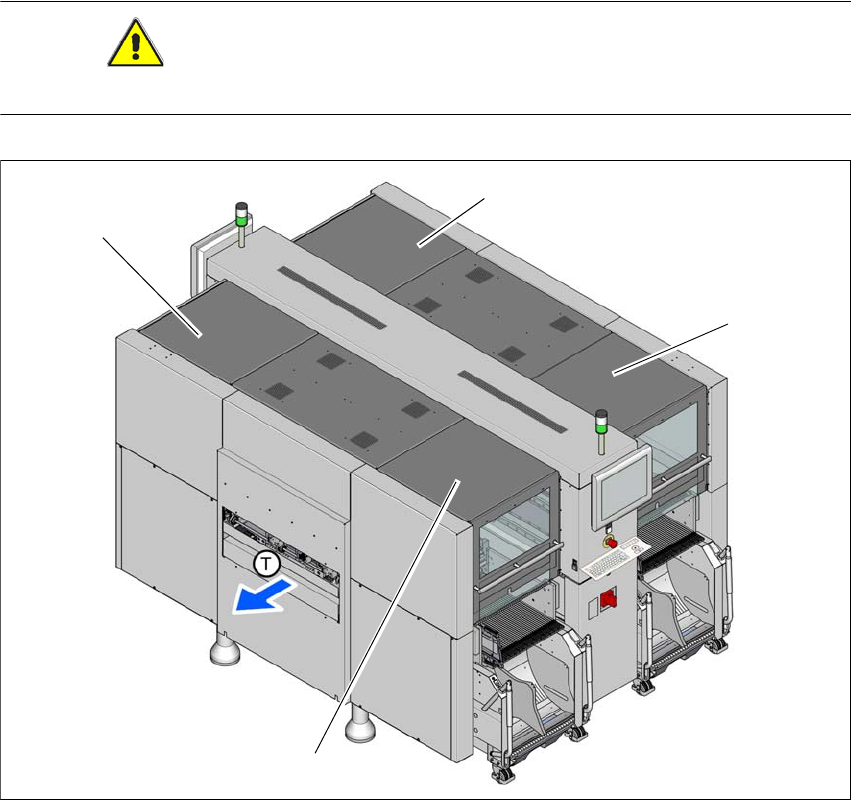
2.7.1 Protective covers
The travel range of the gantries is covered with four movable protective covers. The protective
hoods and covers serve as protective devices which prevent unauthorized access to the inside of
the machine.
CAUTION
Do not stand on or otherwise access the protective hoods and covers. 2
2
Fig. 2.7 - 1 Protective covers
(example of SX4)
(1) Protective cover location 1
(2) Protective cover location 2
(3) Protective cover location 3
(4) Protective cover location 4
(4)
(1)
(3)
(2)