00196693-03_UM_SX4DX4_SR706_EN.pdf - 第203页
User Manual SIPLACE SX4/DX4 4 Setting up and commissioning From software version SC.706.xx V ersion 06/2012 EN 4.2 Infrastructure at the installation location 203 4.2.3.5 Connecting the power supply c able 4 Fig. 4.2 - 5…
4 Setting up and commissioning User Manual SIPLACE SX4/DX4
4.2 Infrastructure at the installation location From software version SC.706.xx Version 06/2012 EN
202
4.2.3.4 Mains connection - delivery configuration
The main power connection is configured according to the power supply of the country concerned.
– The machine is configured for voltages of 204V AC, 220V AC or 230V AC.
The machine has a mains power cable WITHOUT plug. 4
4
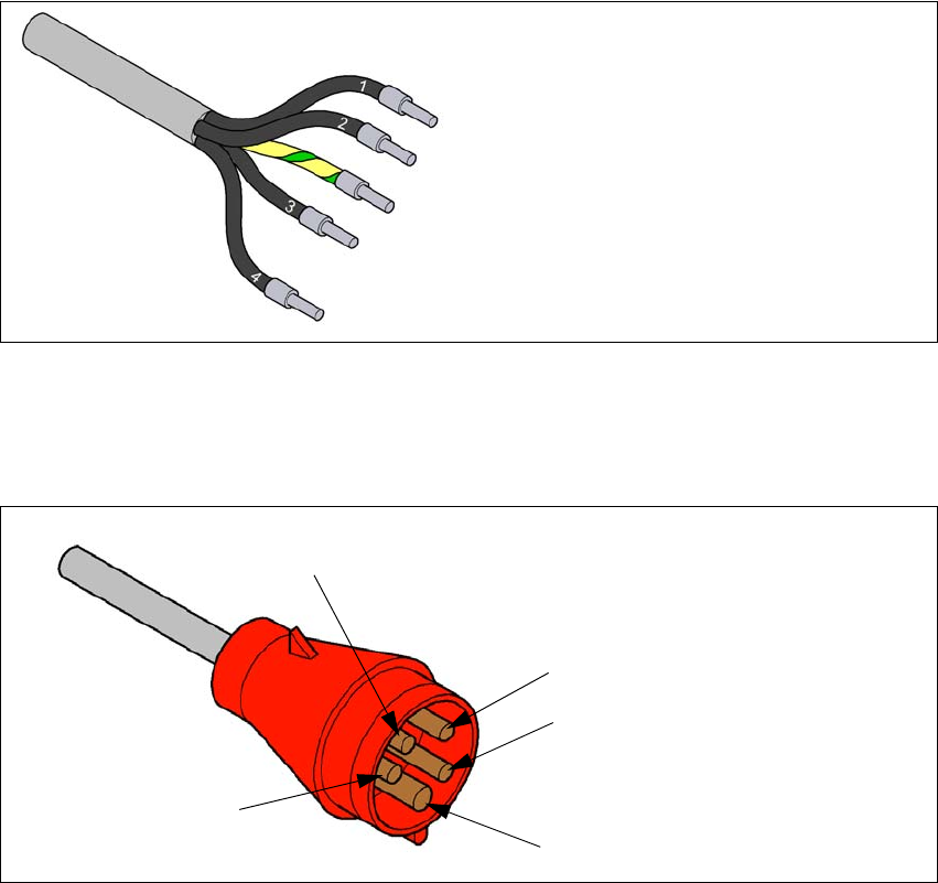
Fig. 4.2 - 3 Description of wires in the mains power cable
– The machine is configured for voltages of 380V AC, 400V AC or 415V AC.
The machine has a mains power cable WITH Cekon plug. 4
4
Fig. 4.2 - 4 Assignment in the Cekon plug
1 = (L1): three-phase
2 = (L2): three-phase
3 = (L3): three-phase
4 = (N): neutral conductor
green/yellow = (PE): conductor
PE
L1
L2
L3
N
User Manual SIPLACE SX4/DX4 4 Setting up and commissioning
From software version SC.706.xx Version 06/2012 EN 4.2 Infrastructure at the installation location
203
4.2.3.5 Connecting the power supply cable
4
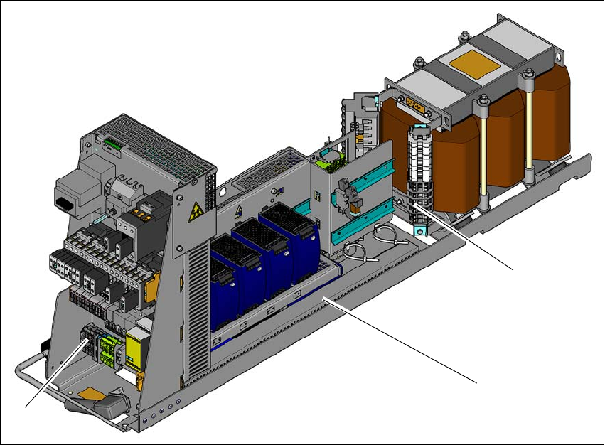
Fig. 4.2 - 5 Terminal panel for connecting the power cable
(1) Terminal panel (primary terminals for the three-phase transformer)
(2) Power supply unit
(3) Mains supply terminals
Crimp a ferrule onto each end of the wire.
Run the mains supply cable to the mains connection terminals (item 3).
Fix the cable to the mains connection terminals (item 3)
(L1): three-phase 4
(L2): three-phase 4
(L3): three-phase 4
(N): neutral conductor 4
(PE): PE conductor 4
Make sure that the bending radius is adequate. The wires must not be kinked.
Fix the mains supply cable with the help of cable ties.
(1)
(2)
(3)
4 Setting up and commissioning User Manual SIPLACE SX4/DX4
4.2 Infrastructure at the installation location From software version SC.706.xx Version 06/2012 EN
204
4.2.3.6 Checking connections to the primary side of the three-phase transformer T1
The primary side of the three-phase transformer must be configured for the relevant supply volt-
age.
Check the terminal strip (1) to make sure that the primary end of the three-phase transformer
is correctly connected for the relevant supply voltage.
4
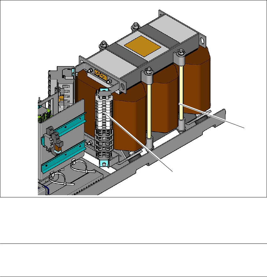
Fig. 4.2 - 6 Terminal panel for the primary side of the three-phase transformer T1
(1) Terminal panel with primary connections for the three-phase transformer T1
(2) Three-phase transformer
PLEASE NOTE 4
The supply networks for North Japan (3 x 200 V~) and for the USA (
3 x 208 V~) are connected to the terminals for 3 x 204 V~.
The following overview shows the connection options for the primary voltages of the three-phase
transformer.
(1)
(2)