00196920-07_SIPLACE_Pro_FeatureDescription_DE_EN.pdf - 第20页
SIPLACE Pro Fe ature Des cription Ausgabe 05/2014 Edit ion 20 2.3 Features in combi nation w ith station software 603 (V4.1) 2.3.1 Support of SIPL A CE D1 and SIPL A CE D2 S IPLACE Pro 4.1 sup ports the new m achine t yp…
SIPLACE Pro Feature Description Ausgabe 05/2014 Edition
19
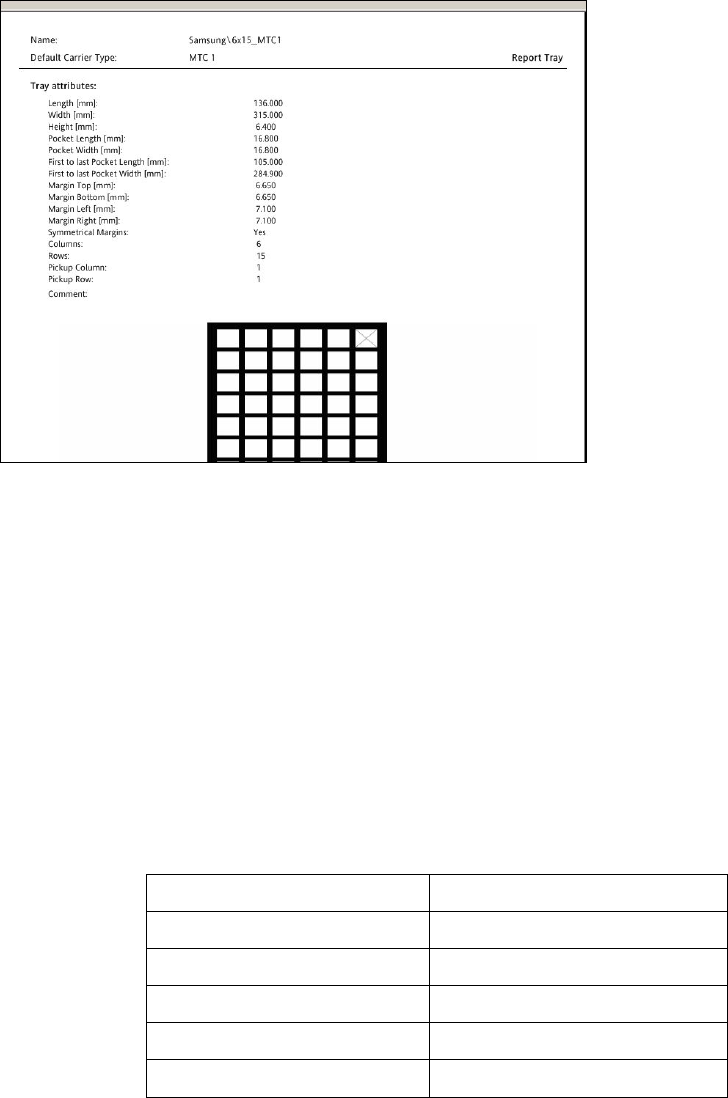
2.2.11.6 Tray Report
The tray report contains all necessary data necessary to describe a tray:
● Tray view
● Default Carrier Type
● Tray basic data (L, W, H)
● First to last pocket
● Margins
● Grid size (columns, rows)
● Pocket size
● Pick-up (columns, rows)
● Comments
NOTICE
The tray report can only be created for one tray only. A multi-
selection of several trays for
one report is not possible.
The tray report can be accessed via:
● the context menu
● the button "Report" in the toolbar if a tray is open
SIPLACE Pro Feature Description Ausgabe 05/2014 Edition
20
2.3 Features in combination with station software 603 (V4.1)
2.3.1 Support of SIPLACE D1 and SIPLACE D2
SIPLACE Pro 4.1 supports the new machine types D1, D2 and D3 and D4 of the D series and the
machine types X2, X3, X4 of the X series. All machine types are running with station software 603.
2.3.1.1 Single Gantry Machine SIPLACE D1
The SIPLACE D1 could also run as cost-efficient machine with one head module and/or one table.
Following head combinations are on the individual locations possible:
Gantry 1 / Location 1 Gantry 1 / location 2
P&P C&P6
P&P C&P12
P&P -
- C&P6
- C&P12
2.3.2 Support of WPC 4 for SIPLACE D1
The WPC4 can only be used together with the SIPLACE D1. The WPC 4 is the follower of the
WPC 3 and could only be setup on location 1 of the SIPLACE D1. The WPC consists of a tower
with 28 levels and covers tracks 1-60. The WPC 4 has a higher performance due to new drives, the
reduced acceleration of Y and Z axis and the handling of higher components.

SIPLACE Pro Feature Description Ausgabe 05/2014 Edition
21
2.3.3 High Force Twin Head
The High Force Twin Head is able to place components with a placement force up to 30N. This is
valid for all machines of platform II and II+. For machines that are running with a station software
smaller than SW 603 the Twin Head is able to place components up to 30 N provided that the Twin
Head is setup as High Force Twin Head on the station.
SIPLACE Pro 4.1 supports following features of the High Force Twin Head:
● The High Force Twin Head is running in X series machines (X2, X3, X4) and the SIPLACE D3
with station software 603.
● Together with the High Force Twin Head the component shape editor has the possibility to
describe component shapes with leads of type "Centering Pin". This lead type is used to place
connectors, sockets etc. For the type "Centering Pin" it is possible to enter the pin height that
influences the overall height of the component shape. The "Centering Pin" type can only be
used with travel profile 32.
● For high placement forces of more than 15N without centering pin you have to use travel
profiles 32 and 26.
2.3.4 Twin Head in Dual Gantry Placement Areas
SIPLACE Pro 4.1 allows for X series machines several Twin Head combinations in placement
areas with two gantries.
SIPLACE X 4
Heads in placement area 1 Heads in placement area 2 Status
Location 1 Loaction 4 Location 2 Location 3
C&P12/6 C&P12/6 TH TH Preferred
C&P6 TH TH C&P6 Preferred
TH TH TH TH Supported
C&P12 TH TH C&P6 Supported
C&P12 TH TH C&P12 Supported
C&P6 TH TH C&P12 Not Supported
C&P20 TH TH C&P20 Not allowed