IPC-TM-650 EN 2022 试验方法--.pdf - 第139页
The Institute for Int erconnecting and Packaging E lectronic Circuits 2215 S anders Road • Northbrook, IL 60062-6135 Material in this T est M ethods Manual was vol untaril y establis hed by T echni cal Committees of the …
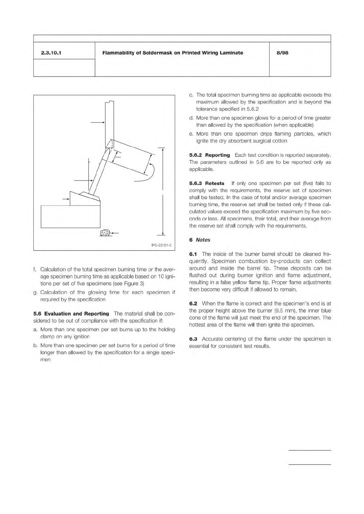
Figure 2 Specimen Mounted in the Test Fixture
Specimen
9.5 mm
19 mm
304 mm
Dry absorbant
surgical cotton
Mounting
Block
Burner
20
o
IPC-TM-650
Number
Subject Date
Revision
Page 3 of 4
2.3.10.1
Flammability
of
Soldermask
on
Printed
Wiring
Laminate
8/98
f.
Calculation
of
the
total
specimen
burning
time
or
the
aver¬
age
specimen
burning
time
as
applicable
based
on
10
igni¬
tions
per
set
of
five
specimens
(see
Figure
3)
g.
Calculation
of
the
glowing
time
for
each
specimen
if
required
by
the
specification
5.6
Evaluation
and
Reporting
The
material
shall
be
con¬
sidered
to
be
out
of
compliance
with
the
specification
if:
a.
More
than
one
specimen
per
set
burns
up
to
the
holding
clamp
on
any
ignition
b.
More
than
one
specimen
per
set
burns
for
a
period
of
time
longer
than
allowed
by
the
specification
for
a
single
speci-
c.
The
total
specimen
burning
time
as
applicable
exceeds
the
maximum
allowed
by
the
specification
and
is
beyond
the
tolerance
specified
in
5.6.2
d.
More
than
one
specimen
glows
for
a
period
of
time
greater
than
allowed
by
the
specification
(when
applicable)
e.
More
than
one
specimen
drips
flaming
particles,
which
ignite
the
dry
absorbent
surgical
cotton
5.
6.2
Reporting
Each
test
condition
is
reported
separately.
The
parameters
outlined
in
5.6
are
to
be
reported
only
as
applicable.
5.
6.3
Retests
If
only
one
specimen
per
set
(five)
fails
to
comply
with
the
requirements,
the
reserve
set
of
specimen
shall
be
tested.
In
the
case
of
total
and/or
average
specimen
burning
time,
the
reserve
set
shall
be
tested
only
if
these
cal¬
culated
values
exceed
the
specification
maximum
by
five
sec¬
onds
or
less.
All
specimens,
their
total,
and
their
average
from
the
reserve
set
shall
comply
with
the
requirements.
6
Notes
6.1
The
inside
of
the
burner
barrel
should
be
cleaned
fre¬
quently.
Specimen
combustion
by-products
can
collect
around
and
inside
the
barrel
tip.
These
deposits
can
be
flushed
out
during
burner
ignition
and
flame
adjustment,
resulting
in
a
false
yellow
flame
tip.
Proper
flame
adjustments
then
become
very
difficult
if
allowed
to
remain.
6.2
When
the
flame
is
correct
and
the
specimen's
end
is
at
the
proper
height
above
the
burner
(9.5
mm),
the
inner
blue
cone
of
the
flame
will
just
meet
the
end
of
the
specimen.
The
hottest
area
of
the
flame
will
then
ignite
the
specimen.
6.3
Accurate
centering
of
the
flame
under
the
specimen
is
essential
for
consistent
test
results.
men
The Institute for Interconnecting and Packaging Electronic Circuits
2215 Sanders Road • Northbrook, IL 60062-6135
Material in this Test Methods Manual was voluntarily established by Technical Committees of the IPC. This material is advisory only
and its use or adaptation is entirely voluntary. IPC disclaims all liability of any kind as to the use, application, or adaptation of this
material. Users are also wholly responsible for protecting themselves against all claims or liabilities for patent infringement.
Equipment referenced is for the convenience of the user and does not imply endorsement by the IPC.
Page 1 of 3
IPC-TM-650
TEST
METHODS
MANUAL
Number
2.3.17.2
Subject
Resin
Flow
of
“N。
Flow”
Prepreg
Date
8/97
Revision
B
Originating
Task
Group
MIL-P-13949
Test
Methods
Task
Group
(7-1
1b)
1
.0
Scope
This
test
method
is
designed
to
measure
the
Resin
Flow
of
“no
flow"
prepreg
used
for
bonding
and
adhe¬
sion
without
formation
of
resin
bead
as
caused
by
flow
of
the
resin.
2
.0
Applicable
Documents
None
3
.0
Test
Specimens
3.1
Size
and
Configuration
A
specimen
shall
consist
of
multiple
plies
of
prepreg
cut
approximately
102
mm
[4.0
in]
x
102
mm
[4.0
in].
If
the
reinforcement
is
a
continuous
fiber
woven
fabric,
the
sides
shall
be
cut
on
a
bias
to
the
fabric
weave.
Unless
otherwise
specified,
the
test
specimen
shall
have
three
plies.
3.2
Quantity
and
Sampling
Unless
otherwise
specified,
the
number
of
specimens
tested
shall
be
as
follows:
For
quali¬
fication
testing,
3
specimens
shall
be
tested,
with
the
pieces
for
each
taken
from
areas
of
the
prepreg
that
represents
the
center
and
both
edges
of
the
material
as
impregnated.
For
lot
testing,
one
specimen
shall
be
tested,
with
the
pieces
ran¬
domly
taken
from
the
prepreg.
Pieces
shall
be
taken
no
less
than
25.4
mm
[1.0
in]
from
the
impregnated
edge.
4
.0
Apparatus
or
Material
4.1
Laminating
Press
Unless
otherwise
specified,
a
lami¬
nating
press
capable
of
maintaining
at
a
temperature
of
171
±
2.8℃
[340
±
5°F]
and
capable
of
providing
a
pressure
of
1
380
土
70
kPa
[200
土
10
psi]
on
the
test
sample,
see
6.1
4.2
Hole
Punch
Hole
cutting
tool,
such
as
a
hole
punch
or
die
set
capable
of
cutting
a
25.4
±
1
.3
mm
[1
.0
土
0.05
in]
hole.
4.3
Materials
4.3.1
Release
material
shall
be
Tedlar
type
(polyvinyl
fluo¬
ride,
PVF),
or
equivalent,
of
0.05
mm
[0.002
in]
thickness,
maximum,
at
least
as
large
as
the
size
of
the
caul
plates.
4.3.2
Any
copper-clad
laminate
of
thickness
between
0.25
mm
[0.010
in]
and
0.38
mm
[0.0151
in]
shall
be
cut
to
approximately
152
mm
x
152
mm
[6.0
in
x
6.0
in].
4.3.3
Conformal
press
pad
material
equivalent
to
0.5
mm
[0.020
in]
cotton
linter
paper,
and
cut
to
approximately
152
mm
x
152
mm
[6.0
in
x
6.0
in].
4.4
Measuring
Microscope
Bausch
and
Lomb,
model
SUB-73
stereozoom
microscope
with
31-16-08
micrometer
disc,
Carl
Zeiss
Stage
Micrometer,
or
equivalent.
4.5
Caul
Plates
Caul
plates
shall
be
3.2
mm
[0.125
in]
thick
and
152
mm
[6.0
in]
square
and
made
from
type
304
steel,
or
equivalent.
4.6
Desiccator
Desiccation
chamber
capable
of
maintain¬
ing
an
atmosphere
of
less
than
30%
RH,
at
23℃
[73°F]-
5
.0
Procedure
5.1
Specimen
Preparation
5.1.1
The
prepreg
shall
be
cut
to
conform
with
the
speci¬
men
size
and
configuration
as
per
3.1
.
5.1.2
If
testing
is
to
be
performed
more
than
10
minutes
after
the
prepreg
has
been
manufactured,
specimens
shall
be
desiccated
for
4
±
1/4
hrs.
prior
to
testing.
5.1.3
Cleaning
of
Copper
Cladding
When
applicable
for
referee
purposes,
clean
the
metallic
cladding
on
the
copper
clad
laminate
by
wiping
the
copper
cladding
with
isopropyl
alcohol.
The
copper
clad
laminate
shall
be
immersed
in
suit¬
able
container
containing
22-23°
BAUME
20
percent
by
vol¬
ume
solution
of
hydrochloric
acid,
technical
grade,
maintained
at
21
±
5.6℃
[170°F
±
10°F]
for
a
period
of
15
seconds.
After
removal
of
the
copper
clad
laminate
from
the
hydrochlo¬
ric
acid,
the
copper
cladding
then
shall
be
rinsed
with
a
cold
water
spray
rinse
for
5
seconds
and
blown
dry
with
filtered,
oil
free,
compressed
air.
5.2
Measurement
5.2.1
A
specimen
shall
be
formed
by
stacking
three
plies
of
prepreg
with
the
grain
of
the
reinforcement
aligned
in
the
same
direction.
Only
if
necessary
to
prevent
ply
slippage,
tack
the
three
plies
together
using
a
standard
soldering
iron
within
one
quarter
inch
from
one
or
more
corners
so
that
the
plies
IPC-TM-650
Number
Subject Date
Revision
Page 2 of 3
8/97
2.3.17.2
Resin
Flow
of
uNo
Flow”
Prepreg
B
lay
flat
to
one
another.
Using
a
25.4
mm
[1.0
in]
diameter
hole
punch,
cut
2
holes
at
least
25.4
mm
[1.0
in]
apart
(See
Figure
1)
in
approximately
the
middle
of
the
specimen.
Caution
should
be
taken
during
cutting
in
order
to
prevent
any
loose
fibers
from
protruding
into
the
clearance
hole.
Measure
the
diameter
of
each
hole
in
3
places,
each
approximately
60°
radial
angle
from
the
others
and
determine
the
average
diam¬
eter
of
the
holes.
5.2.2
Place
the
stack
onto
and
in
the
middle
of
a
1
52
mm
x
152
mm
[6.0
in
x
6.0
in]
copper
clad
laminate
of
thickness
between
0.25
mm
[0.010
in]
and
0.38
mm
[0.015
in]
thick
and
cover
the
stack
with
a
sheet
of
release
film.
Over
the
release
film
place
2
pieces
press
pad
material.
For
referee
purposes,
the
surface
of
the
copper
cladding
shall
be
cleaned
immedi¬
ately
prior
to
lay-up
using
the
procedure
in
paragraph
5.1
.3.
(The
cleaning
is
to
standardize
the
surface
against
which
the
resin
will
flow.)
5.2.3
Place
the
stack
(specimen
plus
laminate,
release,
and
padding)
between
the
two
caul
plates.
Load
the
stack
into
the
laminating
press
maintained
at
1
7
1
°
±
2.8℃
[340°
±
5°F]
and
close
immediately
to
1380
±
70
kPa
[200
±
10
psi].
After
holding
at
full
pressure
for
20
minutes,
minimum,
release
the
pressure
and
remove
the
package.
5.3
Evaluation
After
the
package
has
cooled
to
room
temp,
measure
the
diameter
of
the
punched
holes
at
the
point
of
maximum
and
minimum
diameter
as
formed
by
the
resin
flow.
Subtract
the
average
diameter
of
holes
obtained
in
5.2.1
from
the
maximum
and
minimum
diameters.
5.4
Report
The
results
shall
be
reported
including
the
fol¬
lowing:
1.
Identification
of
specimens
tested.
2.
Resin
flow,
for
each
specimen
tested
in
terms
of
the
maxi¬
mum
flow
and
minimum
flow
in
millimeters
(thousands
of
an
inch)
for
both
die-cut
holes.
6.0
Notes
6.1
Agreement
between
supplier
and
user
other
than
that
specified
in
4.1
may
be
necessary
for
specific
resin
chemistries.
6.2
Desiccator
Conditions
The
Test
Methods
Task
Group
determined
that
a
great
majority
of
test
laboratories
are
unable
to
consistently
hold
the
Relative
Humidity
in
a
desiccator
to
less
than
20%.
Based
on
data
from
participating
company
lab
management,
the
lowest
practically
feasible
RH
for
use
with
the
affected
IPC
Test
Methods
is
30%
maximum.