IPC-TM-650 EN 2022 试验方法--.pdf - 第276页
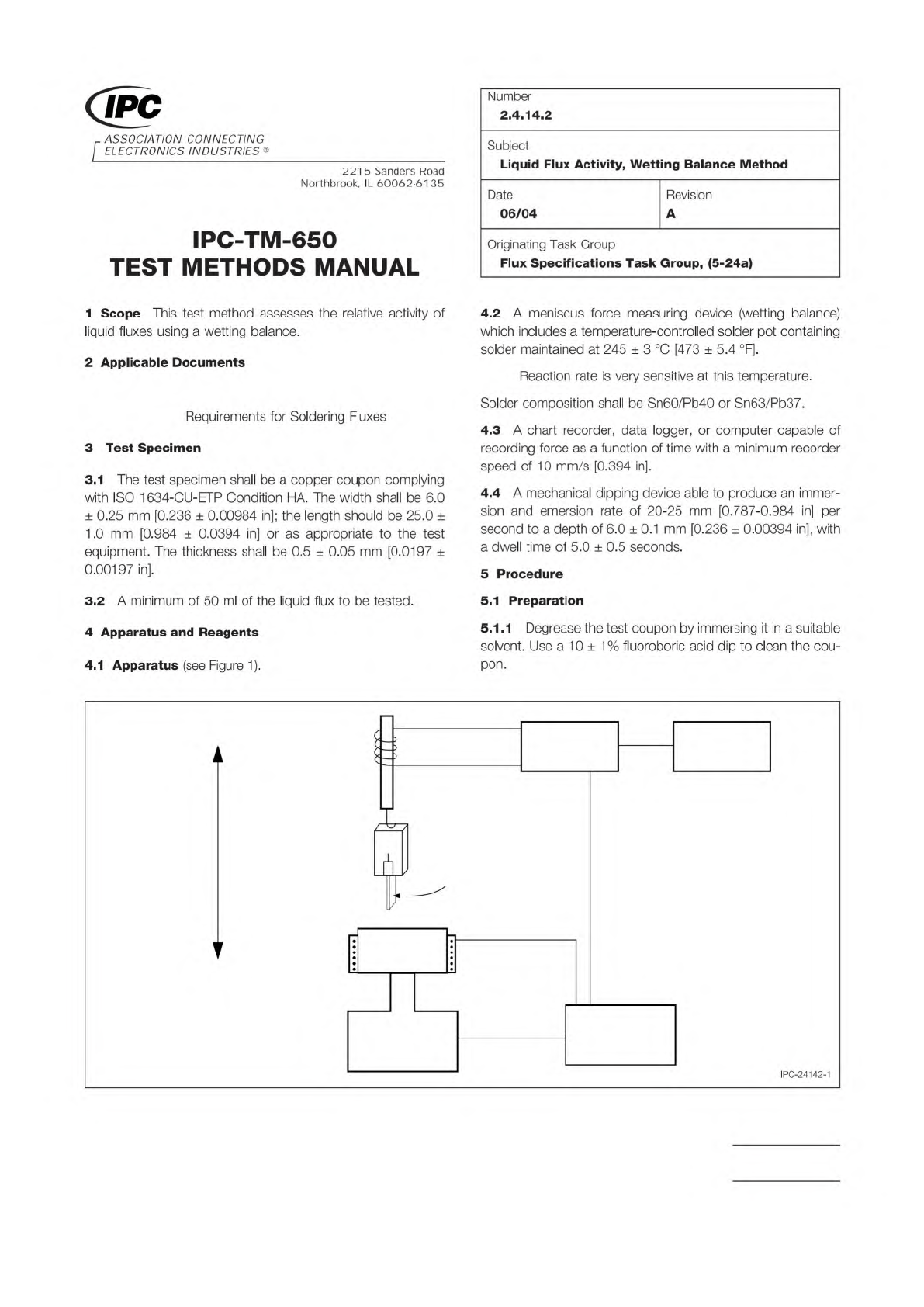
ISO 1634 IPC J-S TD-004 Note: Figure 1 Wett ing Balance Apparatus Chart Recorder Signal Conditioner Controls Solder Bath Heater Clamp Copper Coupon Relative Motion LVDT (Transducer) Material in this T est M ethods Manual…
Note:
IPC-TM-650
Number
Subject Date
Revision
Page 2 of 2
2.4.13.1
Thermal
Stress
of
Laminates
12/94
5.2.1
Fluxing
Immediately
after
removal
from
the
desicca¬
tor,
metal
surfaces
shall
be
cleaned
by
light
abrasion,
or
other
suitable
methods.
Flux
with
rosin
flux
conforming
to
type
R,
MIL-
F-14256.
Let
drain
in
a
vertical
position.
5.2.2
Stressing
Within
10
minutes
of
removal
from
desic¬
cator,
float
the
specimen
for
10
+
1
,
-0
seconds
on
the
sur¬
face
of
a
solder
bath
maintained
at
the
specified
temperature,
measured
at
a
depth
of
25.4
mm
[1
.0
in]
below
the
surface.
The
specimens
shall
be
kept
in
intimate
contact
with
the
sol¬
der
surface
and
agitated
by
gentle
downward
pressure
using
tongs
or
equivalent.
Very
thin
laminates,
typically
under
0.5
mm
[0.020
in]
thick,
are
prone
to
bowing
or
curling
upon
contact
with
solder.
The
following
handling
instructions
apply:
a.
For
etched
specimens,
mount
each
specimen
using
staples
to
a
piece
of
corrugated
board
(*'
cardboard
J,)
approximately
75
x
75
mm
[3.0
x
3.0
in].
b.
For
unetched
single-clad
specimens,
mount
each
speci¬
men
to
a
75
x
75
mm
[3.0
x
3.0
in]
piece
of
corrugated
board
f
'cardboard'
*)
by
slipping
two
opposite
edges
into
slits
cut
parallel
and
38.1
mm
[1.5
in]
apart
in
the
card¬
board.
c.
Unetched
double-clad
specimens
including
those
of
unequal
cladding
thicknesses,
do
not
require
mounting.
5.2.3
The
specimens
shall
be
removed
from
the
bath
and
allowed
to
cool
to
room
temperature.
Mounted
specimens
may
be
removed
from
the
supporting
cardboard.
Clean
the
flux
from
the
specimens
using
appropriate
solvent.
5.3
Evaluation
5.3.1
Etched
or
Unclad
Specimens
Examine
the
speci¬
mens
by
normal
or
corrected
20/20
vision,
using
backlighting
if
necessary.
Record
the
presence
of
charring,
surface
con¬
tamination,
loss
of
surface
resin,
resin
softening,
delamination,
blistering,
weave
exposure,
propagation
of
imperfections,
measling,
crazing,
or
voids.
Determine
the
number
and
dimension
of
any
voids
using
4X
minimum
magnification;
for
referee
purposes,
10X
magnifica¬
tion
shall
be
used.
5.3.2
Clad
Specimens
The
specimen
shall
be
examined
for
any
evidence
of
blistering,
delamination
or
other
damage.
During
the
solder
exposure,
any
apparent
event
that
is
evi¬
dence
of
damage,
such
as
the
specimen
exhibiting
a
“bump”
felt
through
the
tongs,
shall
be
recorded
as
a
sign
of
possible
delamination.
5.3.3
For
referee
purposes,
the
etched
or
unetched
speci¬
mens
shall
then
be
microsectioned
in
accordance
with
IPC-
TM-650,
Method
2.1.1
(except
there
are
no
plated-through
holes).
The
microsections
shall
be
examined
for
degradation
(see
5.6.1)
at
a
magnification
of
100X
and
referee
inspection
at
200X.
5.4
Report
Any
observed
degradation
to
the
unetched
or
etched
or
unclad
specimens
shall
be
reported.
The
number
and
location
of
voids
shall
be
reported
for
each
specimen.
Results
of
referee
microsection
examination
will
take
prece¬
dence
over
visual
examination.
6.0
Note
Automatic
(gang
mounting)
microsectioning
tech¬
niques
may
be
used.
6.1
Desiccator
Conditions
The
Test
Methods
Task
Group
determined
that
a
great
majority
of
test
laboratories
are
unable
to
consistently
hold
the
Relative
Humidity
in
a
desiccator
to
less
than
20%.
Based
on
data
from
participating
company
lab
management,
the
lowest
practically
feasible
RH
for
use
with
the
affected
IPG
Test
Methods
is
30%
maximum.
ISO 1634
IPC J-STD-004
Note:
Figure 1 Wetting Balance Apparatus
Chart
Recorder
Signal
Conditioner
Controls
Solder
Bath
Heater
Clamp
Copper
Coupon
Relative
Motion
LVDT
(Transducer)
Material in this Test Methods Manual was voluntarily established by Technical Committees of IPC. This material is advisory only
and its use or adaptation is entirely voluntary. IPC disclaims all liability of any kind as to the use, application, or adaptation of this
material. Users are also wholly responsible for protecting themselves against all claims or liabilities for patent infringement.
Equipment referenced is for the convenience of the user and does not imply endorsement by IPC.
Page 1 of 3
r
ASSOCIATION
CONNECTING
/
ELECTRONICS
INDUSTRIES
®
221
5
Sanders
Road
Northbrook,
IL
60062-6135
IPC-TM-650
TEST
METHODS
MANUAL
1
Scope
This
test
method
assesses
the
relative
activity
of
liquid
fluxes
using
a
wetting
balance.
2
Applicable
Documents
Requirements
for
Soldering
Fluxes
3
Test
Specimen
3.1
The
test
specimen
shall
be
a
copper
coupon
complying
with
ISO
1634-CU-ETP
Condition
HA.
The
width
shall
be
6.0
土
0.25
mm
[0.236
土
0.00984
in];
the
length
should
be
25.0
±
1
.0
mm
[0.984
±
0.0394
in]
or
as
appropriate
to
the
test
equipment.
The
thickness
shall
be
0.5
±
0.05
mm
[0.0197
士
0.00197
in].
3.2
A
minimum
of
50
ml
of
the
liquid
flux
to
be
tested.
4
Apparatus
and
Reagents
4.1
Apparatus
(see
Figure
1).
Number
2.4.14.2
Subject
Liquid
Flux
Activity,
Wetting
Balance
Method
Date
Revision
06/04
A
Originating
Task
Group
Flux
Specifications
Task
Group,
(5-24a)
4.2
A
meniscus
force
measuring
device
(wetting
balance)
which
includes
a
tern
peratu
re-control
led
solder
pot
containing
solder
maintained
at
245
±
3
[473
土
5.4
°F].
Reaction
rate
is
very
sensitive
at
this
temperature.
Solder
composition
shall
be
Sn60/Pb40
or
Sn63/Pb37.
4.3
A
chart
recorder,
data
logger,
or
computer
capable
of
recording
force
as
a
function
of
time
with
a
minimum
recorder
speed
of
10
mm/s
[0.394
in].
4.4
A
mechanical
dipping
device
able
to
produce
an
immer¬
sion
and
emersion
rate
of
20-25
mm
[0.787-0.984
in]
per
second
to
a
depth
of
6.0
±
0.1
mm
[0.236
±
0.00394
in],
with
a
dwell
time
of
5.0
±
0.5
seconds.
5
Procedure
5.1
Preparation
5.1
.1
Degrease
the
test
coupon
by
immersing
it
in
a
suitable
solvent.
Use
a
10
±
1%
fluoroboric
acid
dip
to
clean
the
cou¬
pon.
IPC-24142-1
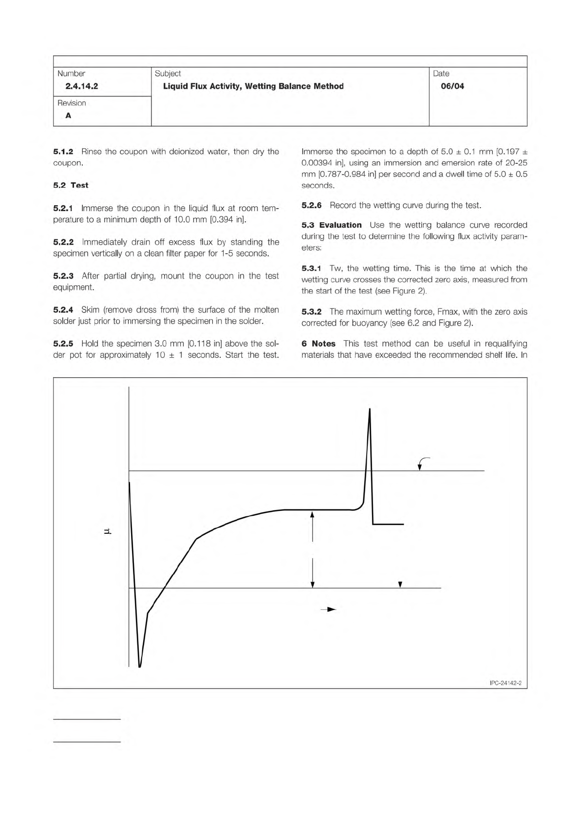
Figure 2 Wetting Balance Curve
TIME
FORCE ( N)
0
Instrument Zero
Corrected Zero
Fmax
T
w
IPC-TM-650
Page 2 of 3
Number
2.4.14.2
Revision
A
Subject
Liquid
Flux
Activity,
Wetting
Balance
Method
Date
06/04
5.1.2
Rinse
the
coupon
with
deionized
water,
then
dry
the
coupon.
5.2
Test
5.2.1
Immerse
the
coupon
in
the
liquid
flux
at
room
tem¬
perature
to
a
minimum
depth
of
10.0
mm
[0.394
in].
5.2.2
Immediately
drain
off
excess
flux
by
standing
the
specimen
vertically
on
a
clean
filter
paper
for
1
-5
seconds.
5.2.3
After
partial
drying,
mount
the
coupon
in
the
test
equipment.
5.2.4
Skim
(remove
dross
from)
the
surface
of
the
molten
solder
just
prior
to
immersing
the
specimen
in
the
solder.
5.2.5
Hold
the
specimen
3.0
mm
[0.1
18
in]
above
the
sol¬
der
pot
for
approximately
10
±
1
seconds.
Start
the
test.
Immerse
the
specimen
to
a
depth
of
5.0
土
0.1
mm
[0.197
±
0.00394
in],
using
an
immersion
and
emersion
rate
of
20-25
mm
[0.787-0.984
in]
per
second
and
a
dwell
time
of
5.0
土
0.5
seconds.
5.2.6
Record
the
wetting
curve
during
the
test.
5.3
Evaluation
Use
the
wetting
balance
curve
recorded
during
the
test
to
determine
the
following
flux
activity
param¬
eters:
5.3.1
Tw,
the
wetting
time.
This
is
the
time
at
which
the
wetting
curve
crosses
the
corrected
zero
axis,
measured
from
the
start
of
the
test
(see
Figure
2).
5.3.2
The
maximum
wetting
force,
Fmax,
with
the
zero
axis
corrected
for
buoyancy
(see
6.2
and
Figure
2).
6
Notes
This
test
method
can
be
useful
in
requalifying
materials
that
have
exceeded
the
recommended
shelf
life.
In
IPC-24142-2