IPC-TM-650 EN 2022 试验方法--.pdf - 第262页
Figure 7 Corners Su pports R1 R1 R2 Supporting Jacks or Blocks Figure 8 Highest Point Measurement Measure at This Point Measure at This Point R2 R2 R1 IPC-TM-650 Page 5 of 5 Number 2.4.22 Subject Bow and Twist (Percentag…
1 Scope
This test method defines the procedure for deter-
mining the bond strength of metal foils that are 18 microns
thick or greater clad flexible dielectric material as nominally
defined being measured with a 90° peel.
2 Applicable Documents
None
3 Test Specimens
If a statistically sound evaluation by a
given supplier can prove that die cut and etched specimens
differ, the preparation giving the lower measurement can be
the only preparation tested. In case of conflict, the die cut
sample will be used as the referee method. The sample
preparation will be the same for as received, after solder and
after aging.
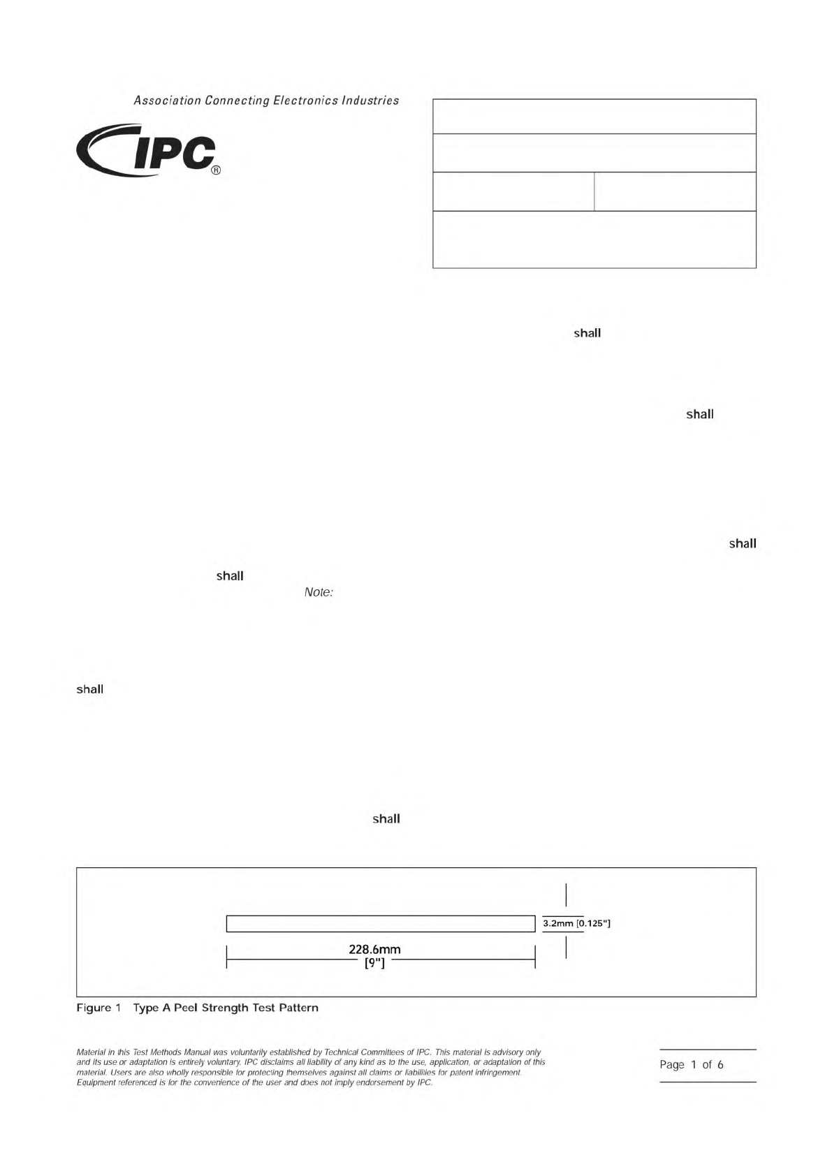
3.1 Type A – Etched Specimen
3.1.1
The test specimen consist of an etched conduc-
tor pattern in accordance with Figure 1.
Conductors
are 3.2 mm wide by 228.6 mm long [0.125 in wide by
9 in long].
3.1.2
A minimum of four specimens, two from the machine
direction (MD) and two from the transverse direction (TD),
be prepared for each of the procedure Methods A, C,
E. If a statistically sound evaluation by a given supplier can
prove that MD and TD measurements differ, the direction giv-
ing the lower measurement can be the only direction tested. If
the two directions are the same, only the MD direction needs
to be tested. In the event a test specimen tears during test-
ing, another test specimen will be prepared to replace it.
3.1.3
For double clad laminate, a separate sample unit
be prepared and tested for each side.
3.2 Type B – Die Cut Specimen
3.2.1
The test specimen consist of a strip of clad flex-
ible material 12.7 mm wide by 228.6 mm long [1/2 in wide by
9 in long].
3.2.2
A minimum of four specimens, two from the machine
direction and two from the transverse direction,
be pre-
pared for each of the procedure Methods B, D, F. If a statis-
tically sound evaluation by a given supplier can prove that MD
and TD measurements differ, the direction giving the lower
measurement can be the only direction tested. If the two
directions are the same, only the MD direction needs to be
tested.
3.2.3
For double clad laminate, a separate sample unit
be prepared and tested for each side. The metal foil on the
non-test side may remain to provide stability to prevent tent-
ing of the specimen from the German Wheel (free wheel rotary
drum). Both samples must be the same with respect to being
with or without the non-test side metal foil.
4 Test Equipment
4.1 Testing Machine
Power driven testing machine,
crosshead autographic type, or an equivalent constant speed
drive machine.
4.2 Sample Cutter
Thwing Albert sample cutter, Model
No. JDC-50, or equivalent.
4.3 Test Fixture
Free wheeling rotary drum (Figure 2), slid-
ing plate (Figure 3), or equivalent. The referee fixture will be a
152.4 mm [6.0 in] diameter free wheeling rotary drum.
IPC-249-1
▼
▼
▼
▼
3000 Lakeside Drive, Suite 309S
Bannockburn, IL 60015-1249
IPC-TM-650
TEST METHODS MANUAL
Number
2.4.9
Subject
Peel Strength, Flexible Dielectric Materials
Date
04/14
Revision
E
Originating Task Group
Flexible Circuits Test Methods Subcommittee
(D-15)
Association
Connecting
Electronics
Industries
shall
shall
Note:
shall
shall
shall
3.2mm
[0.125"]
Figure
1
Type
A
Peel
Strength
Test
Pattern
228.6mm
-
[9"]
-
Material
/n
this
Test
Methods
Manual
was
voluntarily
established
by
Technical
Committees
of
I
PC.
This
material
/s
advisory
only
and
"s
use
or
adaptation
,
s
entirely
voluntary.
IPC
disclaims
all
liability
of
any
kind
as
to
the
use,
application,
or
adaptation
of
this
material.
Users
are
also
wholly
responsible
for
protecting
themselves
against
all
claims
or
liabilities
for
patent
infringement.
Equipment
referenced
/s
for
the
convenience
of
the
user
and
does
not
imply
endorsement
by
IPC.
Page
1
of
6
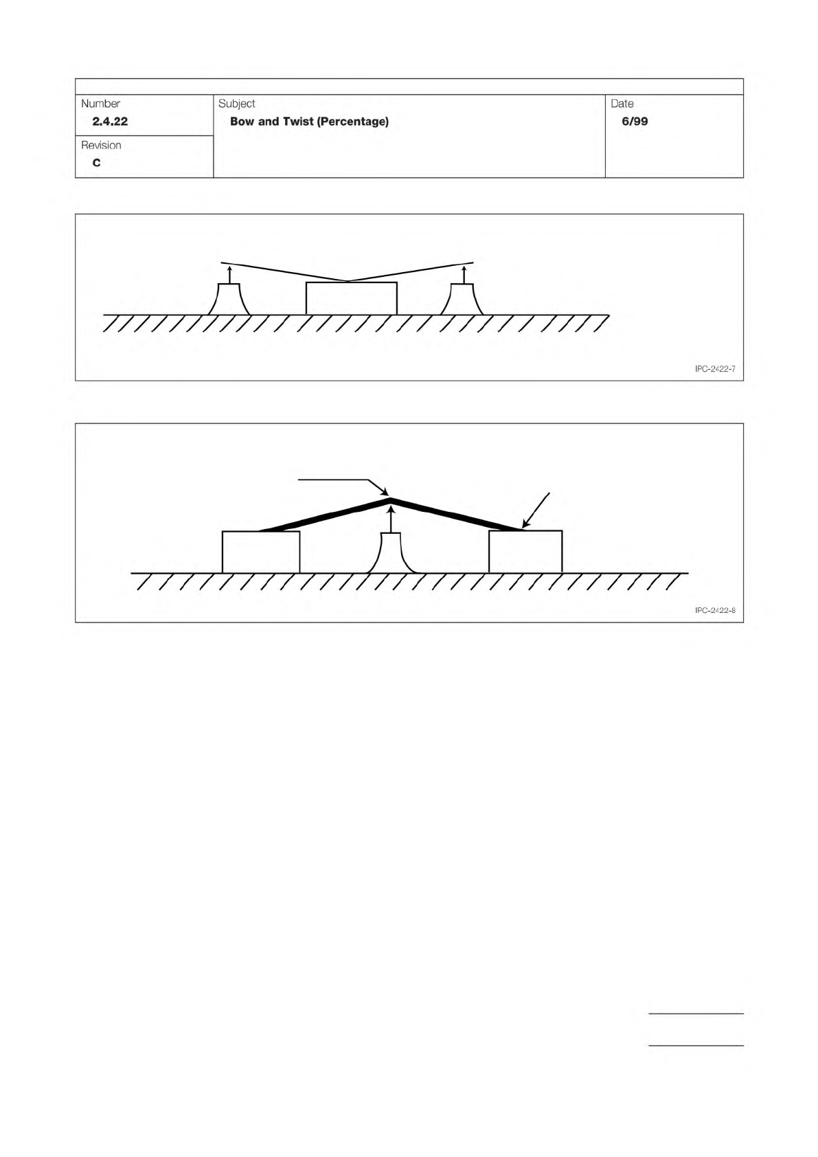
Figure 7 Corners Supports
R1 R1
R2
Supporting Jacks or Blocks
Figure 8 Highest Point Measurement
Measure at
This Point
Measure at
This Point
R2
R2
R1
IPC-TM-650
Page 5 of 5
Number
2.4.22
Subject
Bow
and
Twist
(Percentage)
Date
6/99
Revision
C
///////////
//////
/
/////////
I
PC-2422-7
I
PC-2422-8
None
Figure 1
Figure 2
The Institute for Interconnecting and Packaging Electronic Circuits
2215 Sanders Road • Northbrook, IL 60062-6135
Material in this Test Methods Manual was voluntarily established by Technical Committees of the IPC. This material is advisory only
and its use or adaptation is entirely voluntary. IPC disclaims all liability of any kind as to the use, application, or adaptation of this
material. Users are also wholly responsible for protecting themselves against all claims or liabilities for patent infringement.
Equipment referenced is for the convenience of the user and does not imply endorsement by the IPC.
Page 1 of 2
IPC-TM-650
TEST
METHODS
MANUAL
1
.0
Scope
This
method
covers
the
measurement
of
bow
and
twist
by
maximum
vertical
displacement
of
an
unre¬
strained
panel
of
either
cut
to
size
panels
or
finished
rigid
printed
boards
including
single-
and
double-sided,
multilayer,
and
the
rigid
segments
of
rigid
flex
printed
circuits.
This
test
method
is
only
applicable
to
laminates
greater
than
or
equal
to
0.5
mm
[0.020
in]
in
thickness.
This
test
method
can
also
be
used
after
etching
or
after
thermal
stress
with
requirements
as
agreed
between
user
and
vendor.
2
.0
Applicable
Documents
3
.0
Test
Specimen
The
test
specimen
for
incoming
inspection
shall
be
300
x
300
mm
±
2
mm
[12
x
12
in
±
0.08
in]
in
size.
For
smaller
panel
sizes
and
finished
printed
wiring
boards,
use
actual
size.
A
minimum
of
three
specimens
is
required
per
sample,
when
evaluating
pressed
laminate
sheets.
4
.0
Apparatus
4.1
Sample
Shear
4.2
Granite
Surface
Plate
or
Equivalent
4.3
Feeler
Gauges
or
Equivalent
4.4
Micrometer
5
.0
Test
Procedure
5.1
Preparation
of
the
Test
Specimen
5.1.1
For
laminate
sheet,
the
test
specimens
are
to
be
cut
in
such
a
fashion
as
to
minimize
mechanical
flexing.
5.1.2
For
cut
to
size
panels
or
printed
wiring
boards,
use
actual
size.
5.1.3
Mark
the
specimen
for
traceability.
No
mechanical
or
chemical
pre-cleaning
is
permitted
on
the
specimens.
5.2
Measurement
of
Bow
and
Twist
Number
2.4.22.1
Subject
Bow
and
Twist
—
Laminate
Date
Revision
5/93
C
Originating
Task
Group
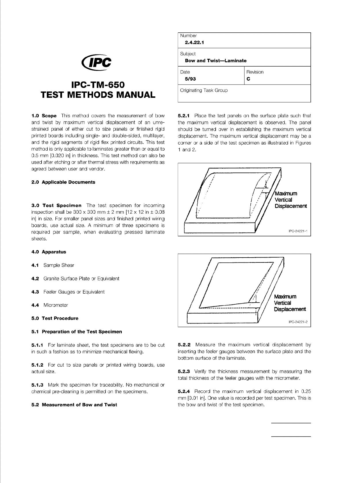
5.2.1
Place
the
test
panels
on
the
surface
plate
such
that
the
maximum
vertical
displacement
is
observed.
The
panel
should
be
turned
over
in
establishing
the
maximum
vertical
displacement.
The
maximum
vertical
displacement
may
be
a
corner
or
a
side
of
the
test
specimen
as
illustrated
in
Figures
1
and
2.
5.2.2
Measure
the
maximum
vertical
displacement
by
inserting
the
feeler
gauges
between
the
surface
plate
and
the
bottom
surface
of
the
laminate.
5.2.3
Verify
the
thickness
measurement
by
measuring
the
total
thickness
of
the
feeler
gauges
with
the
micrometer.
5.2.4
Record
the
maximum
vertical
displacement
in
0.25
mm
[0.01
in].
One
value
is
recorded
per
test
specimen.
This
is
the
bow
and
twist
of
the
test
specimen.