IPC-TM-650 EN 2022 试验方法--.pdf - 第714页
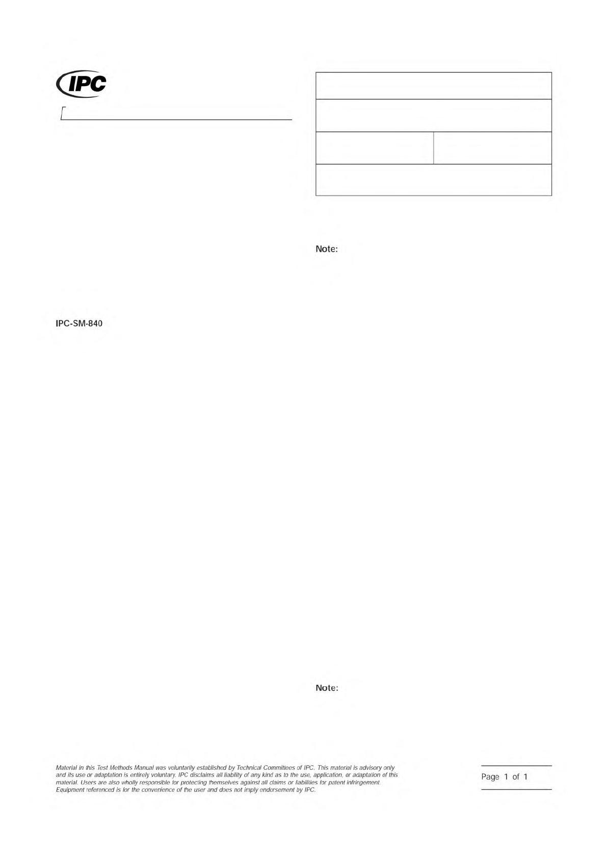
IPC-CC-830 FED-STD-141 Note: 75 mm [2.95 in] 4.7 mm [0.185 in] 38 mm [1.50 in] 19 mm [0.748 in] 6.30 mm [0.248 in] 2.3 0.13 mm DIA [0.091 0.005 in DIA] Hole 0.75 0.08 mm DIA [0.029 0.003 in DIA] 0.75 mm [0.029 in MIN] 0.…
1 Scope
This test method is used to determine the resis-
tance of the applied solder mask to reverting to liquid when
exposed to high humidity at a specific time and temperature
condition. This test method evaluates the stability of a cured
solder mask that has been applied to a printed board under
storage (nonoperating) conditions.
2 Applicable Documents
Qualification and Performance of Permanent
Solder Mask
3 Test Specimens
Three copper clad laminates, approxi-
mately 10 cm x 10 cm [3.94 in x 3.94 in], coated with solder
mask and cured according to the supplier’s recommenda-
tions.
4 Equipment
4.1 Desiccator
At least 25 cm [9.84 in] in diameter
4.2 Potassium Sulfate
Reagent grade potassium sulfate
4.3 Cotton Swabs
4.4 Oven
Capable of maintaining temperature up to 100 °C
[212 °F]
4.5 Test Chamber
Capable of maintaining a constant tem-
perature of 97 ± 2 °C [206.6 ± 3.6 °F] with 94 ± 4% relative
humidity.
4.6 High Temperature Silicone Grease
5 Procedures
5.1 Desiccator Method
5.1.1
Prepare a saturated solution of distilled or deionized
water and potassium sulfate [35 grams per 100 mL] at a tem-
perature of 97 ± 2 °C [206.6 ± 3.6 °F]. Pour the solution into
the desiccator just below the ceramic plate. Crystals of potas-
sium sulfate should remain visible in the saturated solution
during testing.
Relative humidity is not to exceed 98%.
5.1.2
Place the three test specimens on the ceramic plate in
the desiccator so that they are not touching each other.
5.1.3
Seal the desiccator with high temperature silicone
grease and close the desiccator.
5.1.4
Place the desiccator in the oven maintained at 97 ± 2
°C [206.6 ± 3.6 °F].
5.1.5
Allow the desiccator, containing the test specimens,
to remain in the oven for 28 days (672 hours).
5.2 Chamber Method
5.2.1
Place the three test specimens in a rack so they do
not touch each other and place the rack into the test cham-
ber. Close the chamber door.
5.2.2
Set the chamber’s parameters at 97 ± 2 °C [206.6 ±
3.6 °F] and 94 ± 4% relative humidity. Activate the test cham-
ber and begin testing.
5.2.3
Allow the specimens to remain in the test chamber for
28 days (672 hours).
5.3 Evaluation
5.3.1
After the required time exposure remove the test
specimens and visually examine the specimens for evidence
of reversion as indicated by softening, chalking, blisters,
cracks, tackiness, loss of adhesion or liquefaction.
5.3.2
Touch (do not wipe) the surface of the solder mask
coating with a swab of absorbent cotton and observe for par-
ticles of the cotton adhering to the coating.
Examination and testing may be done at intervals
within the required exposure time, if there is suspicion of early
failure and evaluation time is critical.
3000 Lakeside Drive, Suite 309S
Bannockburn, IL 60015-1249
IPC-TM-650
TEST METHODS MANUAL
Number
2.6.11
Subject
Solder Mask - Hydrolytic Stability
Date
03/07
Revision
D
Originating Task Group
Solder Mask Performance Task Group (5-33b)
ASSOCIATION CONNECTING
ELECTRONICS INDUSTRIES
®
IPC-SM-840
Note:
Note:
Material
/n
this
Test
Methods
Manual
was
voluntarily
established
by
Technical
Committees
of
I
PC.
This
material
/s
advisory
only
and
"s
use
or
adaptation
,
s
entirely
voluntary.
IPC
disclaims
all
liability
of
any
kind
as
to
the
use,
application,
or
adaptation
of
this
material.
Users
are
also
wholly
responsible
for
protecting
themselves
against
all
claims
or
liabilities
for
patent
infringement.
Equipment
referenced
/s
for
the
convenience
of
the
user
and
does
not
imply
endorsement
by
IPC.
Page
1
of
1

IPC-CC-830
FED-STD-141
Note:
75 mm
[2.95 in]
4.7 mm
[0.185 in]
38 mm
[1.50 in]
19 mm
[0.748 in]
6.30 mm [0.248 in]
2.3
0.13 mm DIA
[0.091
0.005 in DIA]
Hole 0.75
0.08 mm DIA
[0.029
0.003 in DIA]
0.75 mm [0.029 in MIN]
0.75 mm
008 mm [0.029 in 0.003 in MIN]
0.75 mm [0.029 in MIN]
3.2 mm
[0.126 in]
25
1.5 mm
[0.984
0.059 in MIN]
3.8
0.13 mm DIA
[0.150
0.005 in DIA]
HOLE 1.3
0.08 mm DIA
[0.051
0.0031 in DIA]
Figure 1 ‘‘Y’’ Shape Pattern
Material in this Test Methods Manual was voluntarily established by Technical Committees of IPC. This material is advisory only
and its use or adaptation is entirely voluntary. IPC disclaims all liability of any kind as to the use, application, or adaptation of this
material. Users are also wholly responsible for protecting themselves against all claims or liabilities for patent infringement.
Equipment referenced is for the convenience of the user and does not imply endorsement by IPC.
Page 1 of 2
Number
r
ASSOCIATION
CONNECTING
/
ELECTRONICS
INDUSTRIES
221
5
Sanders
Road
Northbrook,
IL
60062-6135
IPC-TM-650
TEST
METHODS
MANUAL
1
Scope
This
test
method
is
to
determine
the
resistance
of
the
applied
conformal
coating
to
reverting
to
liquid
when
exposed
to
high
humidity
at
a
specific
temperature
and
time
condition
for
each
class.
This
test
method
is
to
evaluate
the
quality
of
the
coated
printed
boards
under
storage
conditions
(nonoperating).
2
Applicable
Documents
Qualification
and
Performance
of
Electrical
Insu¬
lating
Compound
for
Printed
Board
Assemblies
Method
4061
(Dry-Through
For
Varnish,
Lac¬
quers
And
Enamels)
3
Test
Specimens
Five
coated
shape
patterns
(see
Figure
1)
containing
two
resistors,
one
with
marking
ink
and
one
with
color
code
bars,
coated
with
conformal
coating
per
the
coating
supplier's
recommendations.
2.6.11.1
(Supersedes
2.6.1
1B
for
Conformal
Coating
Test)
Subject
Hydrolytic
Stability
-
Conformal
Coating
Date
07/00
Revision
Originating
Task
Group
Conformal
Coating
Task
Group
(5-33a)
4
Equipment
4.1
Desiccator
At
least
25
cm
[9.84
in]
in
diameter
4.2
Potassium
Sulfate
Reagent
grade
potassium
sulfate
4.3
Cotton
Swabs
4.4
Oven
Capable
of
maintaining
temperature
up
to
1
00℃
[212°F]-
4.5
Test
Chamber
Capable
of
maintaining
a
constant
tem¬
perature
of
85°
±
2
℃
[185°
±
3.6°F]
with
95
±
4%
relative
humidity
4.6
Soldering
Iron
If
applicable
4.7
High
Temperature
Silicone
Grease
5
.0
Procedures
5.1
Desiccator
Method
5.1.1
Prepare
a
saturated
solution
of
distilled
or
deionized
water
and
potassium
sulfate
(35
grams
per
100
cm3)
at
a
temperature
of
85°
土
2
℃
[185°
±
3.6°F].
Pour
the
solution
into
the
desiccator
just
below
the
ceramic
plate.
Crystals
of
potassium
sulfate
should
remain
visible
in
the
saturated
solu¬
tion
during
testing.
Relative
humidity
is
not
to
exceed
98%.
5.1.2
Place
four
of
the
five
test
specimens
on
the
ceramic
plate
in
the
desiccator
so
that
they
are
not
touching
each
other.
The
fifth
specimen
is
used
as
a
control.
5.1.3
Seal
the
desiccator
with
high
temperature
silicone
grease
and
close
the
desiccator.
5.1.4
Place
the
desiccator
in
the
oven
maintained
at
85°
±
2
℃
[185°
土
3.6°F].
5.1.5
Allow
the
desiccator,
containing
the
test
specimens,
to
remain
in
the
oven
for
1
20
days.
IPC-TM-650
Page 2 of 2
Number
2.6.11.1
Revision
Subject
Hydrolytic
Stability
-
Conformal
Coating
Date
07/00
5.2
Evaluation
5.2.1
During
testing,
examine
the
test
specimens
at
28th,
56th
and
84th
days.
Prior
to
examining
the
test
specimens,
they
shall
be
returned
to
25℃
[77°F]
and
50%
relative
humid¬
ity
for
two
hours.
Evaluate
the
specimens
for
evidence
of
reversion
as
indicated
by
softening,
chalking,
blistering,
crack¬
ing,
tackiness,
loss
of
adhesion
or
liquefaction.
Evaluate
also
legibility
of
the
markings
on
the
board
and/or
the
resistors.
5.2.2
After
the
1
20-day
aging
period,
the
panels
shall
be
returned
to
25℃
[77°F]
and
50%
relative
humidity
and
held
for
seven
days.
The
specimens
shall
be
evaluated
and
compared
with
the
control
specimen
as
per
5.2.1.
The
specimens
shall
also
be
tested
for
tackiness
in
accordance
with
Method
4061
(Dry-Through
For
Varnish,
Lacquers
And
Enamels)
of
FED-
STD-141.
5.3
Chamber
Method
5.3.1
Place
four
of
the
five
test
specimens
into
the
test
chamber,
by
placing
them
in
a
rack
or
hanging,
so
that
they
do
not
touch
each
other.
The
fifth
specimen
is
held
as
a
con¬
trol.
Close
the
chamber
door.
5.3.2
Set
the
chamber's
parameters
at
85°
±
2
℃
[185°
±
3.6°F]
and
95
±
4%
relative
humidity.
Activate
the
test
cham¬
ber
and
begin
testing.
5.3.3
Allow
the
specimens
to
remain
in
the
test
chamber
for
1
20
days.
5.4
Evaluation
5.4.1
During
testing,
examine
the
test
specimens
at
28th,
56th
and
84th
days.
Prior
to
examining
the
test
specimens,
they
shall
be
returned
to
25℃
[77°F]
and
50%
relative
humid¬
ity
for
two
hours.
Evaluate
the
specimens
for
evidence
of
reversion
as
indicated
by
softening,
chalking,
blistering,
crack¬
ing,
tackiness,
loss
of
adhesion
or
liquefaction.
Evaluate
also
legibility
of
the
markings
on
the
board
and/or
the
resistors.
5.4.2
After
the
1
20-day
aging
period,
the
panels
shall
be
returned
to
25℃
[77°F]
and
50%
relative
humidity
and
held
for
seven
days.
The
specimens
shall
be
evaluated
and
compared
with
the
control
specimen
as
per
5.2.1
.
The
specimens
shall
also
be
tested
for
tackiness
in
accordance
with
Method
4061
(Dry-Through
For
Varnish,
Lacquers
And
Enamels)
of
FED-
STD-141.