IPC-TM-650 EN 2022 试验方法--.pdf - 第452页
5.5.4 Ca lculating Average Insertion Loss Slope m a and Intercept b a For ‘‘ N ’’ points between frequency range f 1 to f 2 the average insertion l oss slope a nd intercept are defined as follows in Equations 5-15 to 5-1…
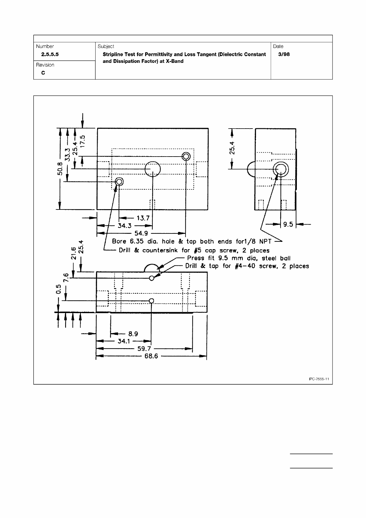
Figure 11 Aluminum Block for Temperature Control and Transfer of Pressure to the Clamp Plates, Fitted with Tapped
Holes for Slide, Embedded Steel Ball, and Tapped for Tubing Fittings for Circulating Fluid
IPC-TM-650
Page 19 of 25

5.5.4 Calculating Average Insertion Loss Slope m
a
and
Intercept b
a
For ‘‘N’’ points between frequency range f1 to
f2 the average insertion loss slope and intercept are defined
as follows in Equations 5-15 to 5-18.
,
avg
=
1
N
Σ
n
,
n
[5-15]
IL
avg
=
1
N
Σ
n
IL(,
n
)
[5-16]
m
A
=
1
N
Σ
n
(,
n
− ,
avg
) ⋅ (IL(,
n
) − IL
avg
)
Σ
(,
n
− ,
avg
)
2
[5-17]
b
A
= IL
avg
− m
A
⋅ ,
avg
[5-18]
Suggested values of f1 and f2 are 1 GHz and 5 GHz respec-
tively.
The slope m
a
is a measure of the total frequency dependent
attenuation, α, which is described in IPC-2141.
Number
2.5.5.12
Subject
Test Methods to Determine the Amount of Signal Loss on
Printed Boards
Date
07/12
Revision
A
IPC-TM-650
Page
24
of
24
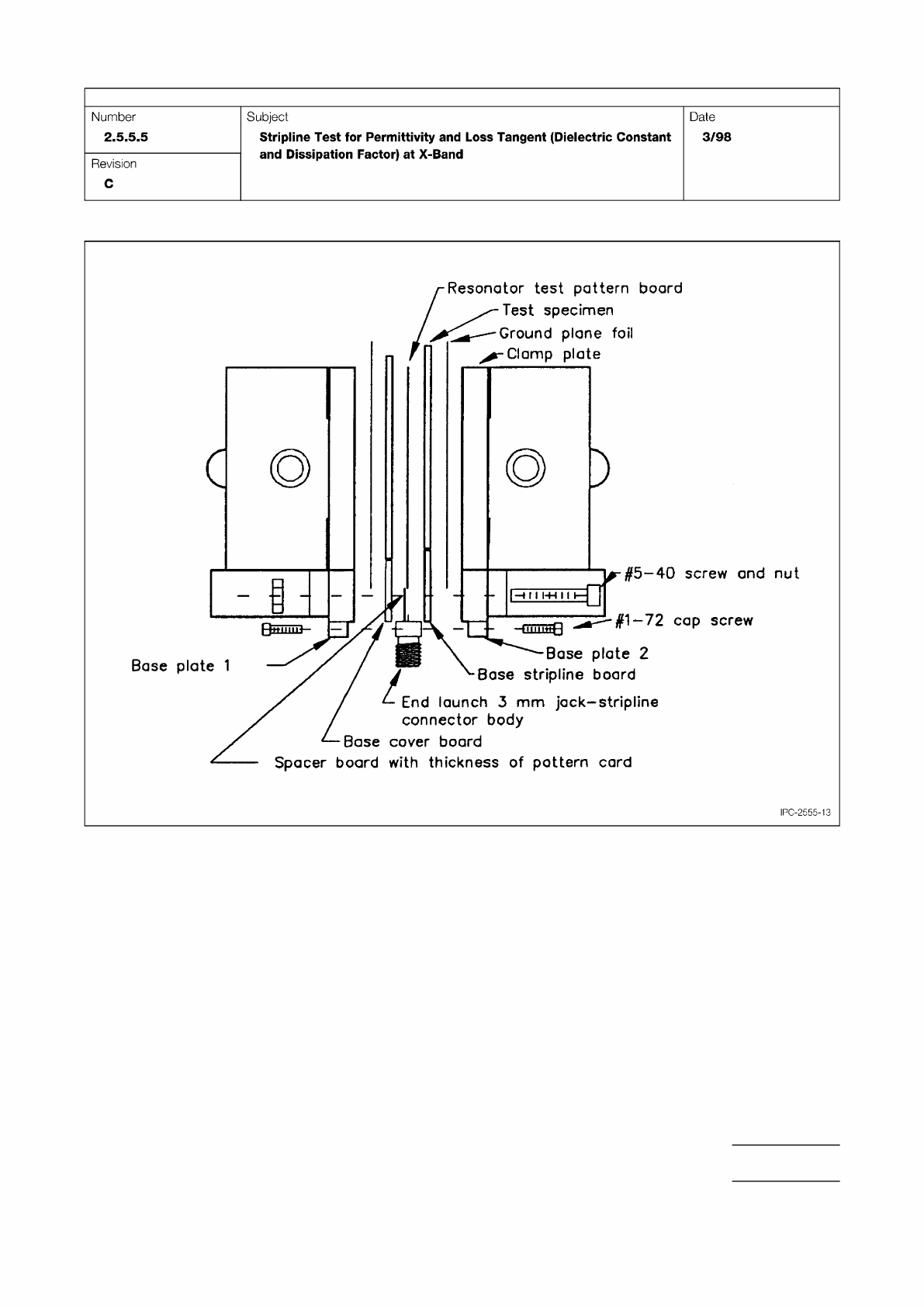
Figure 13 Exploded Side View of Assembly
IPC-TM-650
Page 21 of 25
#5-40
screw
and
nut
i
—
#1-72
cap
screw
三
I
Base
plate
1
IPC-2555-13
Resonator
test
pattern
board
Test
specimen
Ground
plane
foil
Clomp
plate
ase
plate
2
Base
stripline
board
End
launch
3
mm
jack-stripline
connector
body
Base
cover
board
Spacer
board
with
thickness
of
pattern
card
Number
2.5.5.5
Subject
Stripline
Test
for
Permittivity
and
Loss
Tangent
(Dielectric
Constant
and
Dissipation
Factor)
at
X-Band
Date
3/98
Revision
C