IPC-TM-650 EN 2022 试验方法--.pdf - 第233页
Note: The Institute for Int erconnecting and Packaging E lectronic Circuits 2215 S anders Road • Northbrook, IL 60062-6135 Material in this T est M ethods Manual was voluntarily establis hed by T echni cal Committees of …
1 Scope
To determine the number of flexes to conductor
failure of etched flexible printed board conductor patterns.
2 Applicable Documents
None
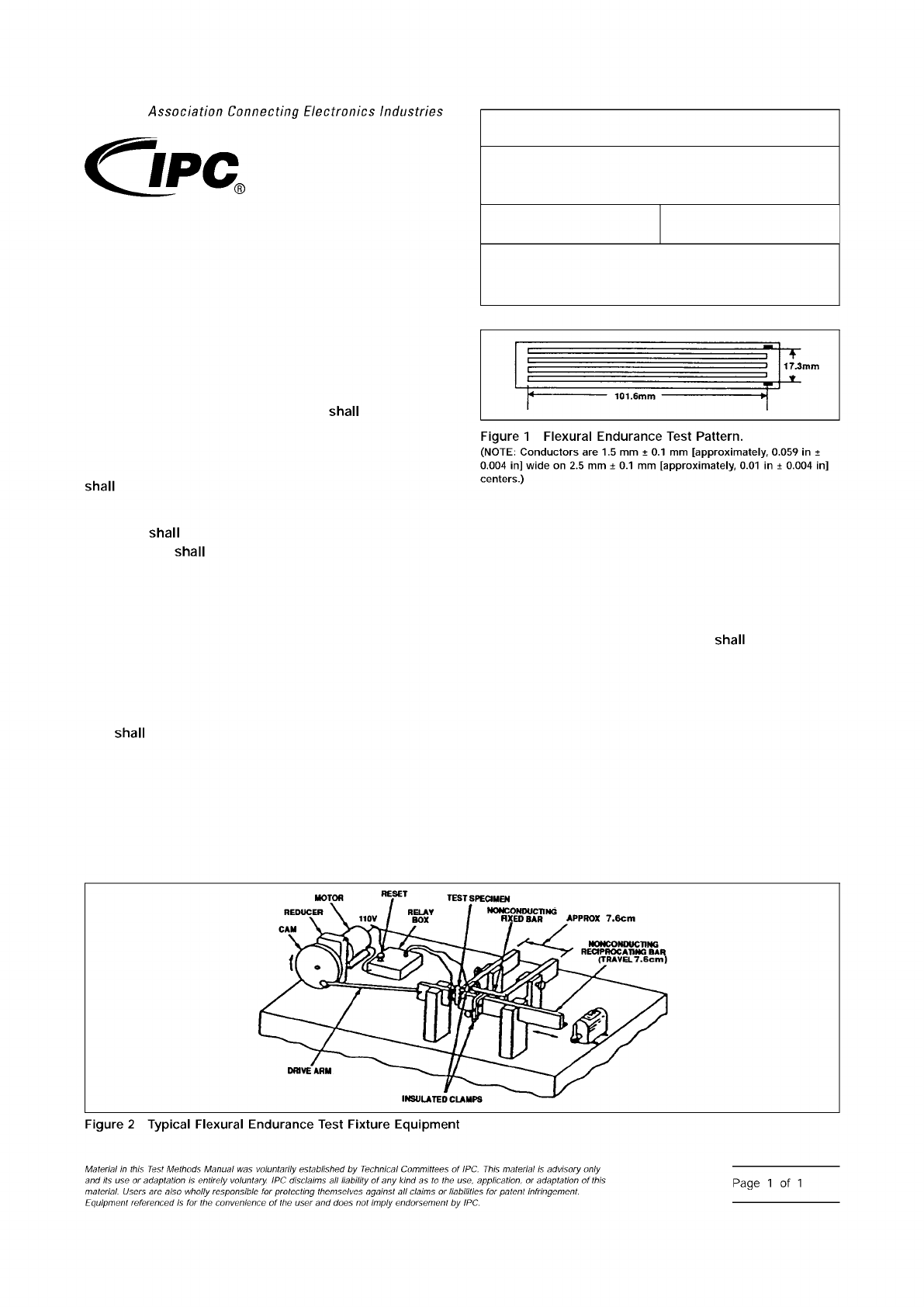
3 Test Specimen
The test specimen consist of an
etched conductor pattern in accordance with Figure 1. A mini-
mum of six specimens with the long dimension of the conduc-
tors oriented in the transverse direction of the base material
be prepared using standard commercial practices.
For double-sided clad constructions, a separate sample
specimen
be prepared for each side. The opposite
(untested) side
be completely etched of copper.
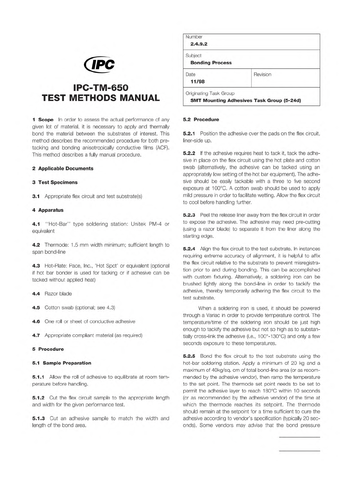
4 Apparatus
Flexural Endurance Tester (see Figure 2) or
equivalent.
5 Procedures
5.1
Examine the etched conductor specimen for any pre-
existing fractures and look for evidence of process anomalies
(such as pin holes and nicks), which could cause premature
fracture. If such fractures or anomalies are found, the speci-
men
be discarded and a new specimen selected.
5.2
Attach (solder, clamp, etc.) a short length of insulated
wire to the extreme ends of the conductor pattern of each of
the six specimens.
5.3
Using the flexure test equipment as seen in Figure 2,
mount the specimen so that the inside diameter of the loop is
6 mm ± 1 mm [approximately, 0.25 in ± 0.04 in] and connect
the two wires to the relay. The horizontal oscillation of the
reciprocating bar causes the flexible test specimen to move in
what can be described as a rolling, flexible action.
5.4
Test three specimens per clad side with the conductor
on the inside of the loop. The reciprocating travel should not
exceed 10 cycles per minute. The loop
travel 25 mm ±
5 mm [effectively, 1 in ± 0.2 in].
5.5
The number of cycles to failure is when electrical discon-
tinuity of the conductor occurs.
5.6
Report the average number of cycles to failure for the
three specimens tested per clad side.
6 Note
Master set of drawings of a similar test fixture as
seen in Figure 2 is available from the IPC office. This fixture is
not commercially available.
IPC-243-1
IPC-243-2
3000 Lakeside Drive, Suite 309S
Bannockburn, IL 60015-1249
IPC-TM-650
TEST METHODS MANUAL
Number
2.4.3
Subject
Flexural Endurance, Flexible Printed Board
Materials
Date
6/11
Revision
E
Originating Task Group
Flexible Circuits Test Methods Subcommittee
(D-15)
Association
Connecting
Electronics
Industries
shall
shall
shall
Figure
1
Flexural
Endurance
Test
Pattern.
(NOTE:
Conductors
are
1.5
mm
±
0.1
mm
[approximately,
0.059
in
±
0.004
in]
wide
on
2.5
mm
±
0.1
mm
[approximately,
0.01
in
±
0.004
in]
centers.)
shall
Figure
2
Typical
Flexural
Endurance
Test
Fixture
Equipment
Material
M
this
历
sf
Methods
Manual
was
voluntarily
established
by
Technical
Committees
of
IPC.
This
material
is
advisory
only
and
its
use
or
adaptation
is
entirely
voluntary.
IPC
disclaims
liability
of
any
kind
as
to
the
use,
application,
or
adaptation
of
this
material.
Users
are
also
wholly
responsible
for
protecting
themselves
against
claims
or
liabililies
for
patent
infringement.
Equipment
referenced
/s
for
fhe
convenience
of
the
user
and
does
not
imply
endorsement
by
IPC.
Page
1
of
1
Note:
The Institute for Interconnecting and Packaging Electronic Circuits
2215 Sanders Road • Northbrook, IL 60062-6135
Material in this Test Methods Manual was voluntarily established by Technical Committees of the IPC. This material is advisory only
and its use or adaptation is entirely voluntary. IPC disclaims all liability of any kind as to the use, application, or adaptation of this
material. Users are also wholly responsible for protecting themselves against all claims or liabilities for patent infringement.
Equipment referenced is for the convenience of the user and does not imply endorsement by the IPC.
Page 1 of 2
IPC-TM-650
TEST
METHODS
MANUAL
1
Scope
In
order
to
assess
the
actual
performance
of
any
given
lot
of
material,
it
is
necessary
to
apply
and
thermally
bond
the
material
between
the
substrates
of
interest.
This
method
describes
the
recommended
procedure
for
both
pre¬
tacking
and
bonding
anisotropically
conductive
films
(ACF).
This
method
describes
a
fully
manual
procedure.
2
Applicable
Documents
3
Test
Specimens
3.1
Appropriate
flex
circuit
and
test
substrate(s)
4
Apparatus
4.1
"Hot-Bar”
type
soldering
station:
Unitek
PM-4
or
equivalent
4.2
Thermode:
1
.5
mm
width
minimum;
sufficient
length
to
span
bond-line
4.3
Hot-Plate:
Pace,
Inc.,
'Hot
Spot'
or
equivalent
(optional
if
hot
bar
bonder
is
used
for
tacking
or
if
adhesive
can
be
tacked
without
applied
heat)
4.4
Razor
blade
4.5
Cotton
swab
(optional;
see
4.3)
4.6
One
roll
or
sheet
of
conductive
adhesive
4.7
Appropriate
compliant
material
(as
required)
5
Procedure
5.1
Sample
Preparation
5.1.1
Allow
the
roll
of
adhesive
to
equilibrate
at
room
tem¬
perature
before
handling.
5.1.2
Cut
the
flex
circuit
sample
to
the
appropriate
length
and
width
for
the
given
performance
test.
5.1.3
Cut
an
adhesive
sample
to
match
the
width
and
length
of
the
bond
area.
Number
2.4.9.2
Subject
Bonding
Process
Date
Revision
11/98
Originating
Task
Group
SMT
Mounting
Adhesives
Task
Group
(5-24d)
5.2
Procedure
5.2.1
Position
the
adhesive
over
the
pads
on
the
flex
circuit,
liner-side
up.
5.2.2
If
the
adhesive
requires
heat
to
tack
it,
tack
the
adhe¬
sive
in
place
on
the
flex
circuit
using
the
hot
plate
and
cotton
swab
(alternatively,
the
adhesive
can
be
tacked
using
an
appropriately
low
setting
of
the
hot
bar
equipment).
The
adhe¬
sive
should
be
easily
tackable
with
a
three
to
five
second
exposure
at
1
00℃.
A
cotton
swab
should
be
used
to
apply
mild
pressure
in
order
to
facilitate
wetting.
Allow
the
flex
circuit
to
cool
before
handling
further.
5.2.3
Peel
the
release
liner
away
from
the
flex
circuit
in
order
to
expose
the
adhesive.
The
adhesive
may
need
pre-cutting
(using
a
razor
blade)
to
separate
it
from
the
liner
along
the
starting
edge.
5.2.4
Align
the
flex
circuit
to
the
test
substrate.
In
instances
requiring
extreme
accuracy
of
alignment,
it
is
helpful
to
affix
the
flex
circuit
relative
to
the
substrate
to
prevent
misregistra¬
tion
prior
to
and
during
bonding.
This
can
be
accomplished
with
custom
fixturing.
Alternatively,
a
soldering
iron
can
be
brushed
lightly
along
the
bond-line
in
order
to
tackify
the
adhesive,
thereby
temporarily
adhering
the
flex
circuit
to
the
test
substrate.
When
a
soldering
iron
is
used,
it
should
be
powered
through
a
Variac
in
order
to
provide
temperature
control.
The
temperature/time
of
the
soldering
iron
should
be
just
high
enough
to
tackify
the
adhesive
but
not
so
high
as
to
substan¬
tially
cross-link
the
adhesive
(i.e.,
100°-130℃)
and
only
a
few
seconds
exposure
to
these
temperatures.
5.2.5
Bond
the
flex
circuit
to
the
test
substrate
using
the
hot-bar
soldering
station.
Apply
a
minimum
of
20
kg
and
a
maximum
of
40kg/sq.
cm
of
total
bond-line
area
(or
as
recom¬
mended
by
the
adhesive
vendor),
then
ramp
the
temperature
to
the
set
point.
The
thermode
set
point
needs
to
be
set
to
permit
the
adhesive
layer
to
reach
1
80℃
within
1
0
seconds
(or
as
recommended
by
the
adhesive
vendor)
of
the
time
at
which
the
thermode
reaches
its
setpoint.
The
thermode
should
remain
at
the
setpoint
for
a
time
sufficient
to
cure
the
adhesive
according
to
vendor's
specification
(typically
20
sec¬
onds).
Some
vendors
may
advise
that
the
bond
pressure

IPC-TM-650
Number
Subject Date
Revision
Page 2 of 2
2.4.9.2
Bonding
Process
11/98
should
be
maintained
until
the
adhesive
layer
cools
to
100℃.
Allow
the
test
sample
to
cool
slightly
before
handling.
The
compliant
material
(if
one
is
used)
should
be
placed
between
the
thermode
and
flex
circuit
prior
to
bonding.