IPC-TM-650 EN 2022 试验方法--.pdf - 第221页
5 Procedure 5.1 Ins trument Se tup Prior to the purchase of the Certi- f ie d R e f er e n ce M a te r i a ls ( C R Ms ) , c o nf i rm w it h t h e X RF manufac turer that the inst rument is ca pable of meas uring phosph…
A Certified Reference Material (CRM) covering the measuring
range of the application as described in 5.2.
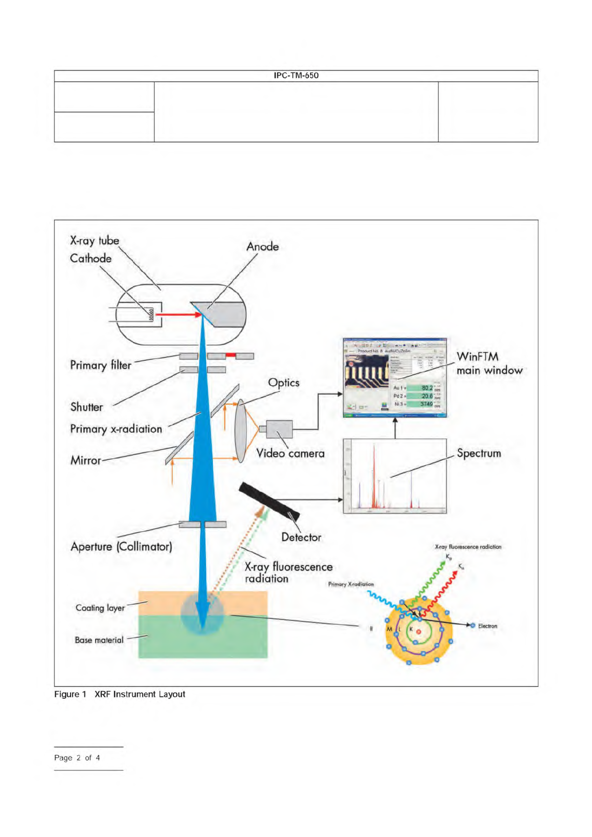
A typical instrument layout is shown in Figure 1.
IPC-2344-1
Number
2.3.44
Subject
Determination of Thickness and Phosphorus Content in
Electroless Nickel (EN) Layers by X-Ray Fluorescence (XRF)
Spectrometry
Date
03/16
Revision
IPC-TM-650
—
Anode
Primary
filter
Shutter
3749
Primary
x-radiation
Spectrum
Mirror
Detector
Aperture
(Collimator)
Primary
X-rodiation
Coating
laye
Electron
Base
material
X-ray
tube
Cathode
Video
camera
X<ay
fluorescence
radiation
WinFTM
main
window
Figure
1
XRF
Instrument
Layout
Page
2
of
4
5 Procedure
5.1 Instrument Setup
Prior to the purchase of the Certi-
fied Reference Materials (CRMs), confirm with the XRF
manufacturer that the instrument is capable of measuring
phosphorus content and obtain details of the recommended
machine set-up and operational procedures.
Instrument setups usually contain a product file that contains
the required measurement specific hardware and software
settings for the application. In addition, the product file con-
tains a calibration file which defines the calibration settings
and certified reference material to be used.
5.2
Typical Instrument setup conditions and measuring
ranges are as follows:
• Aperture Size: 1 mm for both 10kV and 50kV applications.
• Anode Current (I): I=1 mA for 10kV and I=0.15 mA for 50kV
(Anode current setup maximizing achievable instrument
count rates will yield best instrument repeatability, reference
5.3).
• Primary Beam Filter: NO filter for 10 kV and Ni Filter for
50 kV.
• Measurement Time: 120 s for 10kV and 20 s for 50kV.
5.3 Instrument Calibration
Calibration be per-
formed with CRM’s according to the instrument manufacturer
instructions. The CRM’s
be traceable to national labora-
tories. The structure of the reference material
be similar
to the samples under investigation, i.e., NiP/Cu/PCB, Au/NiP/
Cu/PCB or Au/Pd/NiP/Cu/PCB. Individual calibration foils
be used for multilayer coatings. The certified refer-
ence standards
have compositions and thicknesses
similar to the samples to be measured. If desired, it is possible
to calibrate an instrument over the full (low to high) phospho-
rous range. However, optimum accuracy can be achieved by
calibrating each phosphorous range (low, mid, and high)
separately. Each phosphorous content range should be cali-
brated with no less than 4 standards per range. No less than
3 measurements per calibration standard
be performed.
Calibration checks should be performed after each calibration
and periodically by re-measuring the calibration standards. If
the results are within the measurement uncertainty of the
standards and the uncertainty of the measurement itself, no
action is required. If not, a recalibration of the instrument is
required. Typical CRM standards used and results obtained
are summarized in Table 1.
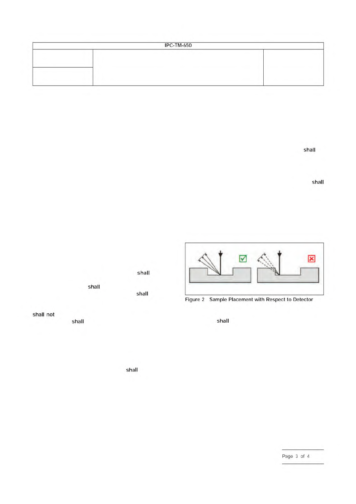
5.4 Sample Placement
There are some basic rules for
positioning specimens. For each measurement, it
be
ensured that the X-ray fluorescence radiation can reach the
detector without obstruction. For flat, unpopulated PCB
boards, this is not a problem.
If populated boards are being measured, the operator
note the position of the detector and position the sample such
that no components are present in locations that would
prevent the radiation emanating from the measurement loca-
tion from reaching the detector, as illustrated schematically in
Figure 2.
The area measured should be flat and not tilted.
5.5 Measurement
XRF equipment operation is instrument
specific and
be in accordance with the instrument
manufacturer’s instructions. Always ensure that the correct
measurement file is selected for the application to be mea-
sured. Typically, instruments will slide the measuring stage out
of the instrument when the measurement chamber is opened.
The test sample is then positioned on the programmable X-Y
stage such that the laser pointer points at the measurement
location. When the measurement chamber is closed, the
stage will automatically retract into the chamber.
IPC-2344-2
Number
2.3.44
Subject
Determination of Thickness and Phosphorus Content in
Electroless Nickel (EN) Layers by X-Ray Fluorescence (XRF)
Spectrometry
Date
03/16
Revision
IPC-TM-650
shall
shall
shall
shall
not
shall
shall
Figure
2
Sample
Placement
with
Respect
to
Detector
shall
Page
3
of
4
IPC-TM-650 Test Methods Manual
The Institute for Interconnecting and Packaging Electronic Circuits
2215 Sanders Road • Northbrook, IL 60062-6135
Material in this Test Methods Manual was voluntarily established by Technical Committees of the IPC. This material is advisory only
and its use or adaptation is entirely voluntary. IPC disclaims all liability of any kind as to the use, application, or adaptation of this
material. Users are also wholly responsible for protecting themselves against all claims or liabilities for patent infringement.
Equipment referenced is for the convenience of the user and does not imply endorsement by the IPC.
Page 1 of 3
IPC-TM-650
TEST
METHODS
MANUAL
1
.0
Scope
The
purpose
of
this
test
is
to
determine
the
peel
strength
of
metal
cladding
to
the
base
laminate
while
at
elevated
temperature;
and
to
evaluate
the
base
laminate
material
after
the
peel
strength
test
is
completed
for
degrada¬
tion
due
to
the
conditioning.
2
.0
Applicable
Documents
Method
2.4.8.
1
,
Peel
Strength,
Metal
Foil
(Keyhole
Method
for
Thin
Laminates)
Method
5.8.3,
Peel
Strength
Test
Pattern
3
.0
Test
Specimens
3.1
Size
and
Configuration
Specimens
shall
be
50.8
mm
x
50.8
mm
[2.0
x
2.0
in]
by
the
thickness
of
the
laminate.
Cladding
test
strips
shall
be
as
specified
(see
5.1
.2).
3.2
Quantity
and
Sampling
Unless
otherwise
specified,
specimens
shall
be
one
lengthwise
for
each
clad
side
and
one
crosswise
for
each
clad
side.
The
outside
25.4
mm
[1
in]
bor¬
der
of
the
parent
sheet
or
panel
shall
be
excluded.
4
.0
Apparatus
or
Material
4.1
Tensile
Tester
A
tensile
strength
tester
equipped
with
a
load
cell,
capable
of
measuring
to
the
nearest
0.0045
kg
[0.01
lbs.]
and
a
light
load
wire
or
chain
and
clamp
at
least
457
mm
[18
in]
long
(its
weight
is
included
in
the
load
cell
cal¬
culation).
The
clamp
jaws
must
cover
the
entire
width
of
each
peel
strip
tab.
Any
equipment
or
apparatus
having
the
described
accuracy,
precision,
and
reproducibility
may
be
used.
4.2
Hot
Fluid
Bath
A
fluid
bath
or
pot
capable
of
maintain¬
ing
the
specified
fluid
at
the
specified
temperature
when
mea¬
sured
2.54
mm
[1
.0
in]
below
the
surface.
4.2.1
Dow
Silicone
Fluid
No.
704,
or
equivalent.
4.3
Specimen
Hold-down
A
suitable
hold-down
clamping
system
equivalent
in
performance
as
that
defined
in
IPC-TM-
650,
Method
2.4.
8.1.
Number
2.4.8.2
Subject
Peel
Strength
of
Metallic
Clad
Laminates
at
Elevated
Temperature
(Hot
Fluid
Method)
Date
Revision
12/94
A
Originating
Task
Group
MIL-P-13949
Test
Methods
Task
Group
(7-1
1b)
4.4
Data
Collection
For
qualification
testing,
a
recording
system
capable
of
permanent
data
retention
incorporated
into
the
test
apparatus.
4.5
Measuring
device
capable
of
measuring
from
0.000
to
12.7
mm
[0.500
in]
to
within
±
0.0025
mm
[0.0001
in].
4.6
Etch
Resist
Materials
or
Systems
4.6.1
Plater's
tape,
or
equivalent,
to
act
as
etch
resist
for
strip
formation
of
the
specified
widths
(see
3.3
and
3.4).
4.6.2
Photoresist
system
(printing,
developing,
and
strip¬
ping).
4.7
Etching
system
capable
of
complete
removal
of
metallic
cladding.
4.8
Circulating
air
oven
capable
of
maintaining
125
土
2
℃
[257
±
3.6°F].
5
.0
Procedure
5.1
Specimen
Preparation
5.1.1
Cut
the
specimens
from
the
laminate
sample.
Speci¬
mens
shall
be
taken
no
closer
than
2.54
mm
[1
.0
in]
from
the
edge
of
the
laminate
sheet
as
manufactured.
5.1.2
Specimens
shall
be
prepared
with
at
least
four
resist
strips
of
3.18
mm
[0.125
in]
width
and
then
etched,
cleaned
and
processed
using
standard
industry
practices
and
equip¬
ment.
For
qualification
and
referee
testing
the
specimen
shall
be
photoimaged
in
accordance
with
the
artwork
shown
in
Method
5.8.3
of
IPC-TM-650
and
reproduced
here
as
Figure
1
,
except
that
tab
ends
are
optional.
Specimens
shall
be
etched
so
that
the
conductor
strips
on
one
specimen
are
in
one
direction
per
Figure
1
.
Double
clad
laminate
shall
have
each
side
tested
using
separate
specimens.
The
opposite
side
cladding
shall
be
either
fully
removed
or
left
fully
clad.
Separate
specimens
for
both
the
warp
and
fill
directions
are
required
for
each
side.
For
referee
testing
the
cladding
on
the
opposite
side
shall
remain.