IPC-TM-650 EN 2022 试验方法--.pdf - 第670页
IPC-TM-650 Page 4 of 4 Number 2.6.3.3 Subject Surface Insulation Resistance, Fluxes Date 06/04 Revision B between two electrified conductors. Both of these conditions must be eliminated for proper testing. 6.2 IPC-B-24 t…
IPC-TM-650
Page 3 of 4
Number
2.6.3.3
Subject
Surface
Insulation
Resistance,
Fluxes
Date
06/04
Revision
B
procedures
listed
below.
The
cleaning
parameters
shall
be
reported
in
the
Qualification
Test
Report
of
J
-STD-004.
5.4.2.
1
The
samples
to
be
cleaned
shall
be
cleaned
with
an
appropriate
environmentally
safe
solvent
or
aqueous
cleaning
medium.
The
use
of
a
commercial
in-line
or
batch
cleaner
is
preferred.
If
this
is
not
available,
the
following
laboratory
clean¬
ing
process
shall
be
followed.
5.4.2.2
Samples
shall
be
cleaned
within
30
minutes
or
less
after
soldering.
For
solvent
or
aqueous
detergent
cleaning,
three
2000
ml
beakers
each
containing
1000
ml
of
solvent
shall
be
used
such
that
one
beaker
serves
as
the
primary
cleaning
stage
and
the
other
two
are
used
for
rinsing
pur¬
poses.
Each
test
coupon
shall
be
agitated
in
each
beaker
for
one
minute.
In
the
case
of
aqueous
detergent,
one
beaker
shall
contain
the
cleaning
agent
and
the
remaining
beakers
shall
contain
deionized
water
for
rinsing
purposes.
Beaker
solutions
shall
be
used
to
clean
or
rinse
a
maximum
of
three
specimens
before
the
solutions
are
replaced.
After
the
clean¬
ing
procedure,
dry
the
samples
for
two
hours
at
50
[122
°F].
Following
cleaning
and
drying,
the
specimens
shall
be
tested
as
outlined
in
5.5
through
5.6.1
.
5.5
Preparation
of
Samples
for
Chamber
Visually
inspect
all
combs
and
discard
(or
replace,
if
possible)
any
combs
with
bridging
of
conductors
or
visible
(at
1
0-30X
with
backlighting)
metallic
debris
between
conductors.
Shield
the
comb
patterns
during
soldering
of
the
connection
points.
Use
water
white
rosin
to
solder
Teflon®-insulated
wires
to
the
con¬
nection
points
of
the
specimens.
Do
not
attempt
to
remove
the
flux
residues.
Connectors
may
be
used
in
lieu
of
soldering
wires
but
are
not
recommended.
In
the
event
of
a
dispute,
the
samples
with
soldered
wires
shall
be
used
as
a
referee.
5.5.1
Place
the
specimens
in
the
environmental
chamber
in
a
vertical
position
such
that
the
air
flow
is
parallel
to
the
direc¬
tion
of
the
board
in
the
chamber.
Set
the
chamber
tempera¬
ture
at
85
土
2
℃
[185
土
3.6
°F]
and
humidity
at
20%
RH
and
allow
the
oven
to
stabilize
at
this
temperature
for
three
hours.
Then
slowly
ramp
the
humidity
to
85
土
2%
over
a
minimum
1
5
minute
period.
Allow
the
specimens
to
come
to
equilibrium
for
at
least
one
hour
before
applying
the
bias
voltage
to
begin
the
test.
If
a
salt
solution
and
desiccator
are
used
for
humidity,
specimens
shall
be
held
for
24
hours
before
beginning
the
test.
5.5.2
Connect
the
45-50v
DC
voltage
source
to
the
speci¬
men
test
points
to
apply
the
bias
voltage
to
all
specimens.
Place
a
1
MQ
current
limiting
resistor
in
series
with
each
test
point.
5.6
Measurements
Measurements
shall
be
made
with
test
specimens
in
the
chamber
under
the
test
conditions
of
tem¬
perature
and
humidity
at
24,
96
and
168
hours.
To
take
these
measurements,
the
45
-
50v
DC
bias
voltage
source
must
be
removed
from
the
test
specimen
and
a
test
voltage
of
-100v
DC
shall
be
applied.
(Test
voltage
polarity
is
opposite
the
bias
polarity.)
5.7
Evaluation
5.7.1
Each
comb
pattern
on
each
test
specimen
shall
be
evaluated
by
the
insulation
resistance
values
obtained
at
96
and
1
68
hours.
If
the
control
coupon
readings
are
less
than
1
000
megohms,
a
new
set
of
test
coupons
shall
be
obtained
and
the
entire
test
repeated.
The
reading
at
24
hours
may
fall
below
the
required
value
provided
that
it
recovers
by
96
hours.
5.7.2
Any
reason
for
deleting
values
(scratches,
condensa¬
tion,
bridged
conductors,
outlying
points,
etc.)
must
be
noted.
Deletion
of
results
for
more
than
two
combs
shall
require
the
test
to
be
repeated.
5.7.3
All
specimens
shall
also
be
examined
under
a
10x
to
30x
microscope
using
backlighting
within
24
hours
of
com¬
pleting
the
testing.
If
the
coupons
are
to
be
held
longer,
they
shall
be
placed
in
Kapak®
or
other
noncontaminating
con¬
tainer
and
stored
in
a
desiccator.
All
samples
must
be
evalu¬
ated
within
seven
days.
If
dendritic
growth
is
observed,
it
shall
be
determined
if
the
dendrite
spans
25%
or
more
of
the
origi¬
nal
spacing.
This
latter
condition
will
constitute
a
failure.
It
should
be
determined
whether
dendritic
growth
is
due
to
con¬
densation
from
the
chamber
(see
6.1).
Visible
discoloration,
corrosion,
or
dendritic
growth
shall
be
reported.
6
Notes
6.1
If
condensation
occurs
on
the
test
specimens
in
the
environmental
chamber
while
the
samples
are
under
voltage,
dendritic
growth
will
occur.
This
can
be
caused
by
a
lack
of
sufficient
control
of
the
humidification
of
the
chamber.
Water
spotting
may
also
be
observed
in
some
chambers
where
the
air
flow
is
from
back
to
front.
In
this
case,
water
condensation
on
the
cooler
chamber
window
can
be
blown
around
the
chamber
as
microdroplets
that
deposit
on
test
specimens
and
cause
dendritic
growth
if
the
spots
bridge
the
distance
IPC-TM-650
Page 4 of 4
Number
2.6.3.3
Subject
Surface
Insulation
Resistance,
Fluxes
Date
06/04
Revision
B
between
two
electrified
conductors.
Both
of
these
conditions
must
be
eliminated
for
proper
testing.
6.2
IPC-B-24
test
board
artwork
and
electronic
data
is
avail¬
able
from
IPG.
6.3
Safety
Observe
all
appropriate
precautions
on
MSDS
for
chemicals
involved
in
this
test
method.
IPC-CC-830
J-STD-004
IPC-A-600
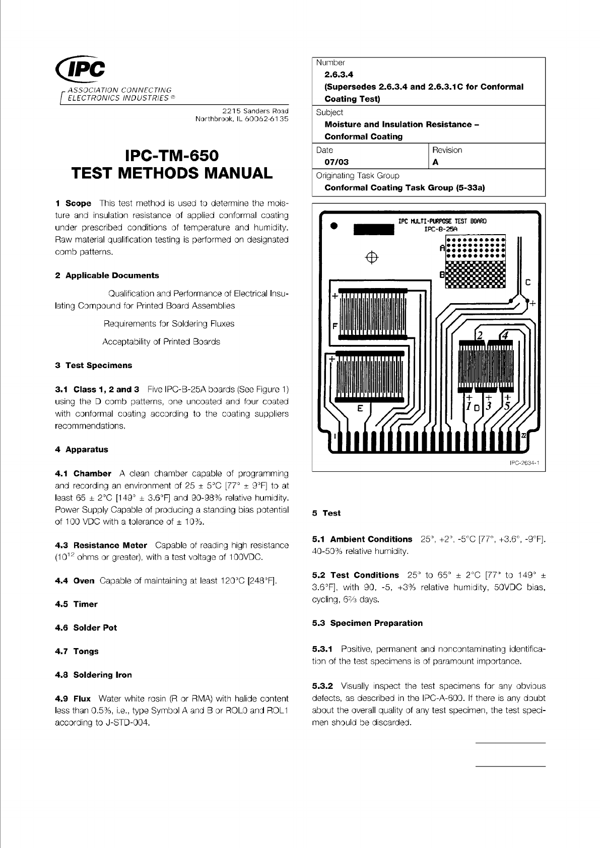
Figure 1 IPC-B-25A Test Board (Test Points on D Pattern
Are Identified)
Material in this Test Methods Manual was voluntarily established by Technical Committees of IPC. This material is advisory only
and its use or adaptation is entirely voluntary. IPC disclaims all liability of any kind as to the use, application, or adaptation of this
material. Users are also wholly responsible for protecting themselves against all claims or liabilities for patent infringement.
Equipment referenced is for the convenience of the user and does not imply endorsement by IPC.
Page 1 of 2
ASSOCIATION
CONNECTING
/
ELECTRONICS
INDUSTRIES®
221
5
Sanders
Road
Northbrook,
IL
60062-61
35
IPC-TM-650
TEST
METHODS
MANUAL
1
Scope
This
test
method
is
used
to
determine
the
mois¬
ture
and
insulation
resistance
of
applied
conformal
coating
under
prescribed
conditions
of
temperature
and
humidity.
Raw
material
qualification
testing
is
performed
on
designated
comb
patterns.
2
Applicable
Documents
Qualification
and
Performance
of
Electrical
Insu¬
lating
Compound
for
Printed
Board
Assemblies
Requirements
for
Soldering
Fluxes
Acceptability
of
Printed
Boards
3
Test
Specimens
3.1
Class
1
,
2
and
3
Five
IPC-B-25A
boards
(See
Figure
1)
using
the
D
comb
patterns,
one
uncoated
and
four
coated
with
conformal
coating
according
to
the
coating
suppliers
recommendations.
4
Apparatus
4.1
Chamber
A
clean
chamber
capable
of
programming
and
recording
an
environment
of
25
±
5
℃
[77°
±
9°F]
to
at
least
65
±
2
℃
[149°
±
3.6°F]
and
90-98%
relative
humidity.
Power
Supply
Capable
of
producing
a
standing
bias
potential
of
100
VDC
with
a
tolerance
of
±
10%.
4.3
Resistance
Meter
Capable
of
reading
high
resistance
(1012
ohms
or
greater),
with
a
test
voltage
of
1
00VDC.
4.4
Oven
Capable
of
maintaining
at
least
120℃
[248°F].
4.5
Timer
4.6
Solder
Pot
4.7
Tongs
4.8
Soldering
Iron
4.9
Flux
Water
white
rosin
(R
or
RMA)
with
halide
content
less
than
0.5%,
i.e.,
type
Symbol
A
and
B
or
ROLO
and
ROL1
according
to
J-STD-004.
Number
2.6.3.4
(Supersedes
2.6.3.4
and
2.6.3.1C
for
Conformal
Coating
Test)
Subject
Moisture
and
Insulation
Resistance
-
Conformal
Coating
Originating
Task
Group
Conformal
Coating
Task
Group
(5-33a)
Date
Revision
07/03
A
5
Test
5.1
Ambient
Conditions
25°,
+2°,
-5℃
[77°,
+3.6°,
-9°F].
40-50%
relative
humidity.
5.2
Test
Conditions
25°
to
65°
土
2
℃
[77°
to
149°
土
3.6°F],
with
90,
-5,
+3%
relative
humidity,
50VDC
bias,
cycling,
6%
days.
5.3
Specimen
Preparation
5.3.1
Positive,
permanent
and
noncontaminating
identifica¬
tion
of
the
test
specimens
is
of
paramount
importance.
5.3.2
Visually
inspect
the
test
specimens
for
any
obvious
defects,
as
described
in
the
IPC-A-600.
If
there
is
any
doubt
about
the
overall
quality
of
any
test
specimen,
the
test
speci¬
men
should
be
discarded.