IPC-TM-650 EN 2022 试验方法--.pdf - 第396页
Figure 6 Base Cover Board w ith Copper Foil Ground Plane Figure 7 Detail of the Supplied Launcher Body , Omni-Spectra Part No. 2070-5068-02 or Equivalent IPC-TM-650 Page 15 o f 25 Number 2.5.5.5 Subject Stripline Test fo…

4.2 Sample Preparation
The required square notch is cut
in the center of the sample width, within ± 0.25 mm, using a
diamond saw or similar stress-free method to form a smooth
bottom of the notch. The slot width should be 0.25 mm
[0.00984 in.].
The crack itself is initiated on each sample with a new 0.23
mm [0.009 in] thick ultra-sharp carbon steel razor blade
(example:
). It
is recommended that the blade be refrigerated or cooled in
liquid nitrogen or in dry ice shortly before use. The razor blade
is then carefully tapped using a small weighted hammer with
sufficient force and control for the crack to initiate on the first
or second try. A new, cool or cold razor blade is recom-
mended for reducing the force needed for crack initiation. A
few specimens in every test lot should first be sacrificed for
operator practice at crack initiation, precisely determining the
hammer force needed for that sample lot to avoid only mak-
ing indentations. The depth of the natural crack generated by
tapping
be a least twice the width of the machined
notch (3X the width of the notch is ideal).
The total depth of the notch plus the depth of the crack
be half the thickness of the sample, within ± 5 percent. There-
fore the depth of the square notch should be 45 percent of
the sample width minus 0.75 mm, ± 0.13 mm. The crack
be sufficiently sharp to ensure that a minimum value
of toughness is obtained during the subsequent 3-point
bending. The actual depths are measured after fracture within
0.5 % accuracy at three locations; at the center of the crack
front, and at the end of the crack front on each surface of the
specimen. The average of these three measurements, which
should be fairly uniform,
be used in the calculations.
Cracks or breaks should be resin-resin, not between resin and
filler.
5 Equipment/Apparatus or Material
5.1 Test Machine
5.1.1
The testing machine used be a constant dis-
placement rate device; an electromechanical screw-driven
machine, or a closed loop feedback-controlled servo-
hydraulic load frame. The stationary and moving rollers used
for the 3-point loading (typically two under each end, and one
on top in the middle of the specimen block opposite the
crack)
each be large enough to avoid excessive inden-
tation of the plastic, however the roller diameter should not
exceed the overall thickness of the specimen.
5.2 Displacement Measurement
5.2.1
The displacement measurement using an internal
displacement transducer having sufficient precision
be
performed using the machines stroke or position transducer.
The fracture test displacement data
be corrected for
system compliance, loading pin penetration and specimen
compression by performing a calibration of the testing sys-
tems as described in ASTM D-5045.
5.2.2
The displacement measurement using an external dis-
placement transducer having sufficient precision
be
performed with the transducer located between the top and
bottom plates, and as close as possible to the load point on
the specimen to ensure displacement accuracy.
5.3 Yield Stress
5.3.1
The yield stress, σ
y
, is determined by the material’s
maximum load in an uniaxial tensile test. Using a constant
stroke rate uniaxial tensile test, the loading time to yield
be within ± 20 percent of the actual loading time observed in
the fracture test. A zero slope to the stress-strain curve is not
required. If a tensile test cannot be performed, then use 0.7
times the compressive yield stress as an approximation.
6 Procedure
6.1 Test Preparation
The specimens and all testing
be performed at 23 °C ± 3 °C. The actual temperature of the
specimen
be recorded. The relative humidity should be
between 30 % and 60 % RH, and be recorded.
6.2 Displacement Correction
Specimen be identi-
cal to the specimen prepared for fracture testing, except with-
out the notch or crack in the middle. This specimen
be
used for single notch bend testing (reference ASTM D5045).
6.3 Testing
6.3.1
The notched specimen that has been pre-cracked is
subjected to loading at a loading rate of 5.0 mm per minute.
6.3.2
The test is performed and the load versus loading
point displacement curve is obtained. In the ideal case, there
is an abrupt drop of load to zero at the instant of crack growth
initiation. If this occurs, then determine the trial K
1c
or K
Q
from
the maximum load. Typically there will be a noticeable devia-
tion from linearity prior to fracture.
Number
2.4.52
Subject
Fracture Toughness of Resin Systems for Base Materials
Date
07/13
Revision
Page 2 of 8
IPC-TM-650
shall
http://www.mcmaster.eom/#3962a4M3qpeql
shall
shall
shall
shall
shall
shall
shall
shall
shall
shall
shall
shall
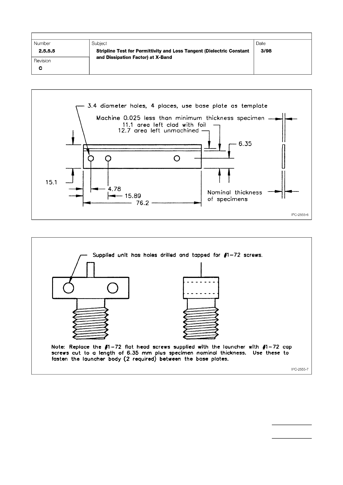
Figure 6 Base Cover Board with Copper Foil Ground Plane
Figure 7 Detail of the Supplied Launcher Body, Omni-Spectra Part No. 2070-5068-02 or Equivalent
IPC-TM-650
Page 15 of 25
Number
2.5.5.5
Subject
Stripline
Test
for
Permittivity
and
Loss
Tangent
(Dielectric
Constant
and
Dissipation
Factor)
at
X-Band
Date
3/98
Revision
C
3,4
diameter
holes,
4
places,
use
base
plate
as
template
上
76.2
IPC-2555-6
Nominal
thickness
of
specimens
Machine
0.025
less
than
minimum
thickness
specimen
11.1
area
left
clad
with
foil
12.7
area
left
unmachined
15.1
J
Note:
Replace
the
#1—72
flat
head
screws
supplied
with
the
launcher
with
#1
—
72
cap
screws
cut
to
a
length
of
6.35
mm
plus
specimen
nominal
thickness.
Use
these
to
fasten
the
launcher
body
(2
required)
between
the
base
plates.
IPC-2555-7
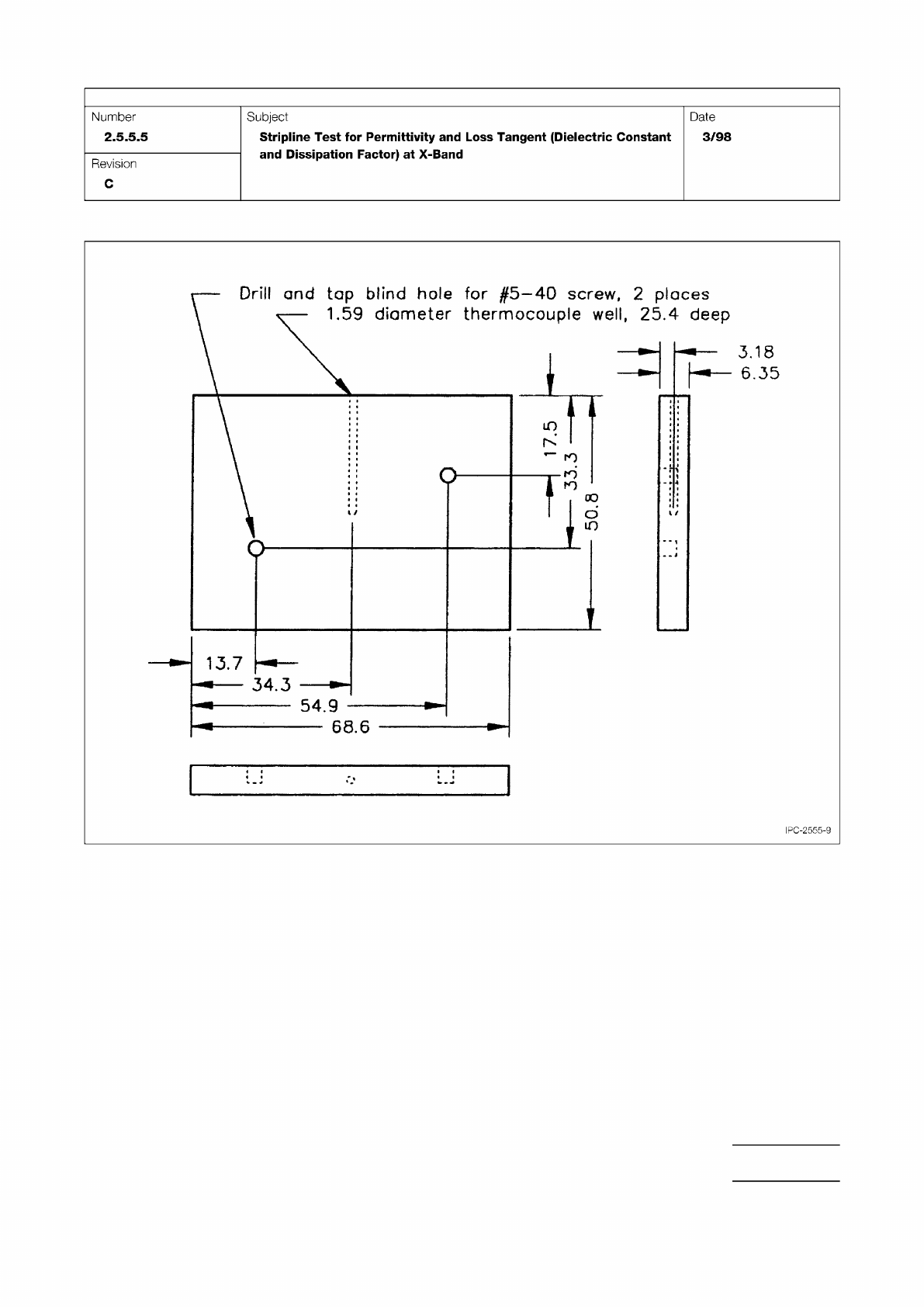
Figure 9 Aluminum Clamping Plate Provided with Tapped Holes for the Pressure Block and a Thermocouple Well
IPC-TM-650
Page 17 of 25
Number
2.5.5.5
Subject
Stripline
Test
for
Permittivity
and
Loss
Tangent
(Dielectric
Constant
and
Dissipation
Factor)
at
X-Band
Date
3/98
Revision
C
IPC-2555-9