IPC-TM-650 EN 2022 试验方法--.pdf - 第671页
IPC-CC-830 J-STD-004 IPC-A-600 Figure 1 IPC -B-25A T est Board ( T est P oints on D Pat tern Are Identified) Material in this T est M ethods Manual was voluntarily establis hed by T echni cal Committees of IPC. Thi s mat …
IPC-TM-650
Page 4 of 4
Number
2.6.3.3
Subject
Surface
Insulation
Resistance,
Fluxes
Date
06/04
Revision
B
between
two
electrified
conductors.
Both
of
these
conditions
must
be
eliminated
for
proper
testing.
6.2
IPC-B-24
test
board
artwork
and
electronic
data
is
avail¬
able
from
IPG.
6.3
Safety
Observe
all
appropriate
precautions
on
MSDS
for
chemicals
involved
in
this
test
method.
IPC-CC-830
J-STD-004
IPC-A-600
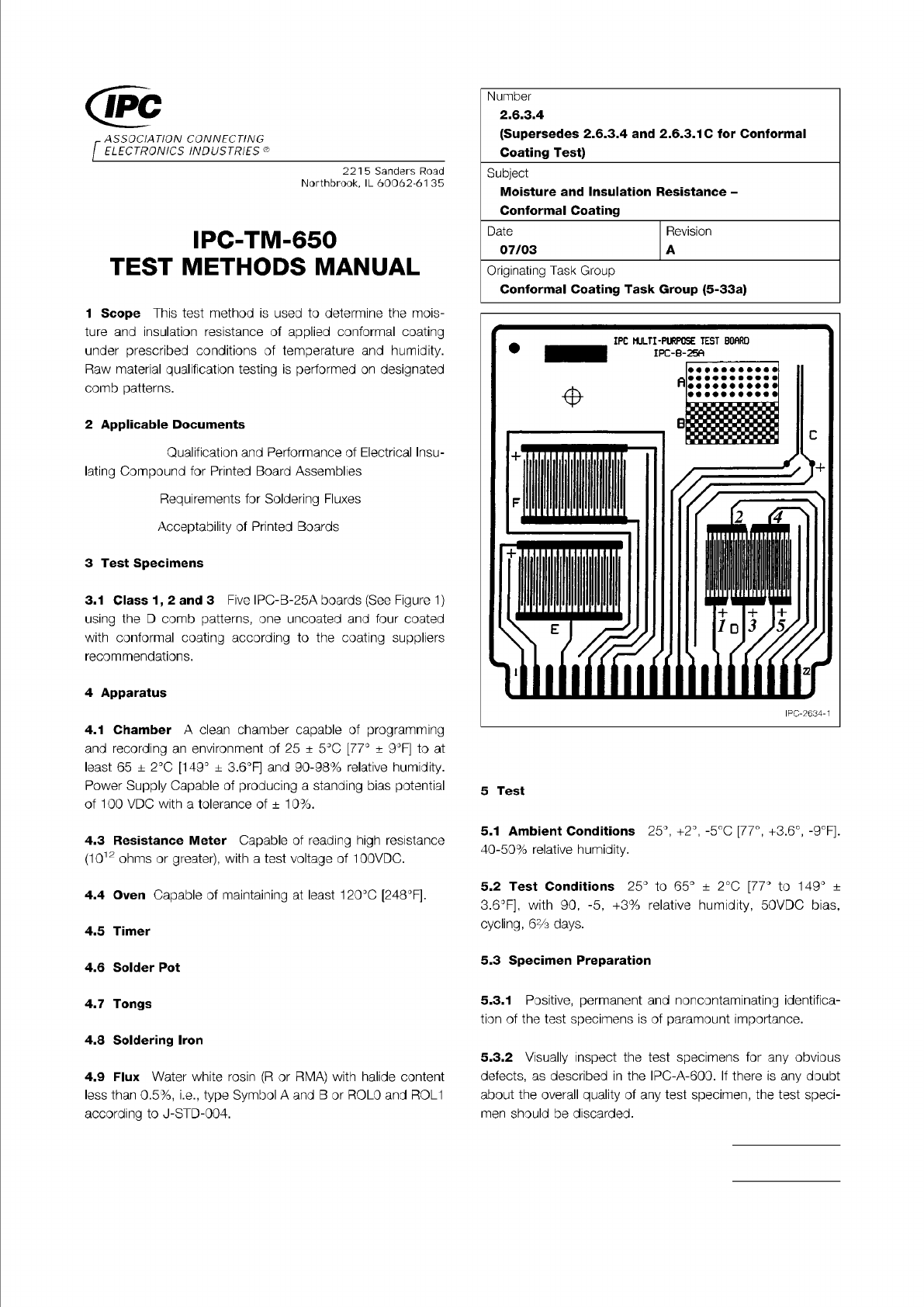
Figure 1 IPC-B-25A Test Board (Test Points on D Pattern
Are Identified)
Material in this Test Methods Manual was voluntarily established by Technical Committees of IPC. This material is advisory only
and its use or adaptation is entirely voluntary. IPC disclaims all liability of any kind as to the use, application, or adaptation of this
material. Users are also wholly responsible for protecting themselves against all claims or liabilities for patent infringement.
Equipment referenced is for the convenience of the user and does not imply endorsement by IPC.
Page 1 of 2
ASSOCIATION
CONNECTING
/
ELECTRONICS
INDUSTRIES®
221
5
Sanders
Road
Northbrook,
IL
60062-61
35
IPC-TM-650
TEST
METHODS
MANUAL
1
Scope
This
test
method
is
used
to
determine
the
mois¬
ture
and
insulation
resistance
of
applied
conformal
coating
under
prescribed
conditions
of
temperature
and
humidity.
Raw
material
qualification
testing
is
performed
on
designated
comb
patterns.
2
Applicable
Documents
Qualification
and
Performance
of
Electrical
Insu¬
lating
Compound
for
Printed
Board
Assemblies
Requirements
for
Soldering
Fluxes
Acceptability
of
Printed
Boards
3
Test
Specimens
3.1
Class
1
,
2
and
3
Five
IPC-B-25A
boards
(See
Figure
1)
using
the
D
comb
patterns,
one
uncoated
and
four
coated
with
conformal
coating
according
to
the
coating
suppliers
recommendations.
4
Apparatus
4.1
Chamber
A
clean
chamber
capable
of
programming
and
recording
an
environment
of
25
±
5
℃
[77°
±
9°F]
to
at
least
65
±
2
℃
[149°
±
3.6°F]
and
90-98%
relative
humidity.
Power
Supply
Capable
of
producing
a
standing
bias
potential
of
100
VDC
with
a
tolerance
of
±
10%.
4.3
Resistance
Meter
Capable
of
reading
high
resistance
(1012
ohms
or
greater),
with
a
test
voltage
of
1
00VDC.
4.4
Oven
Capable
of
maintaining
at
least
120℃
[248°F].
4.5
Timer
4.6
Solder
Pot
4.7
Tongs
4.8
Soldering
Iron
4.9
Flux
Water
white
rosin
(R
or
RMA)
with
halide
content
less
than
0.5%,
i.e.,
type
Symbol
A
and
B
or
ROLO
and
ROL1
according
to
J-STD-004.
Number
2.6.3.4
(Supersedes
2.6.3.4
and
2.6.3.1C
for
Conformal
Coating
Test)
Subject
Moisture
and
Insulation
Resistance
-
Conformal
Coating
Originating
Task
Group
Conformal
Coating
Task
Group
(5-33a)
Date
Revision
07/03
A
5
Test
5.1
Ambient
Conditions
25°,
+2°,
-5℃
[77°,
+3.6°,
-9°F].
40-50%
relative
humidity.
5.2
Test
Conditions
25°
to
65°
土
2
℃
[77°
to
149°
土
3.6°F],
with
90,
-5,
+3%
relative
humidity,
50VDC
bias,
cycling,
6%
days.
5.3
Specimen
Preparation
5.3.1
Positive,
permanent
and
noncontaminating
identifica¬
tion
of
the
test
specimens
is
of
paramount
importance.
5.3.2
Visually
inspect
the
test
specimens
for
any
obvious
defects,
as
described
in
the
IPC-A-600.
If
there
is
any
doubt
about
the
overall
quality
of
any
test
specimen,
the
test
speci¬
men
should
be
discarded.
Note:
Note:
IPC-TM-650
Page 2 of 2
Number
2.6.3.4
Subject
Moisture
and
Insulation
Resistance
-
Conformal
Coating
Date
07/03
Revision
A
5.3.3
One
uncoated
specimen
subjected
to
the
same
pro¬
cessing
(except
coating)
as
the
coated
specimens
shall
be
supplied
with
each
lot
of
samples
as
a
test
control.
5.4
Electrical
Connections
5.4.1
Solder
a
single
strand
PTFE
insulated
wire,
using
the
flux
specified
in
4.9,
to
each
pad
of
the
D
comb
pattern.
These
wires
will
be
used
to
connect
each
pad
of
the
desig¬
nated
comb
pattern
to
polarization
and
insulation
resistance
testing.
When
soldering
the
wires
onto
the
pads
care
should
be
taken
to
ensure
that
the
flux
does
not
splatter
onto
the
combs.
A
simple
off-contact
shield
fixture
should
be
used
to
protect
the
test
patterns
from
the
flux
spitting
during
solder¬
ing.
An
alternate
method
is
to
use
gold
plated
alligator
clips.
5.5
Soldering
Flux
Removal
The
flux
shall
not
be
removed.
If
the
flux
has
contaminated
the
comb
pattern
on
the
control,
the
sample
shall
be
discarded
and
a
new
one
used.
It
cannot
be
cleaned
because
it
will
not
represent
the
cleaning
process
that
was
used
prior
to
conformal
coating
application.
5.6
Specimen
Handling
For
the
remainder
of
the
test,
the
surface
of
the
test
specimens
either
uncoated
or
coated
with
conformal
coating
should
not
be
handled
or
exposed
to
any
other
contaminating
influence.
5.7
Procedure
5.7.1
Condition
the
specimens
at
50
±
2
℃
[122
土
3.6°F]
with
no
added
humidity,
for
a
period
of
24
hours.
5.7.2
Testing
5.7.2.1
Allow
the
specimens
to
cool.
Measure
and
record
the
initial
insulation
resistance
measurements
at
ambient
labo¬
ratory
conditions.
Apply
100
VDC
on
the
specimen's
test
points
with
the
resistance
meter
and
take
the
reading
after
one
minute.
On
the
D
comb
pattern,
test
points
1
,
3
and
5
are
connected
to
the
positive
terminal
and
test
points
2
and
4
are
connected
to
the
negative
terminal
of
the
resistance
meter.
5.7.2.2
Place
specimens
in
a
chamber,
in
the
vertical
posi¬
tion
and
under
a
condensation
drip
shield.
Each
chamber
load
shall
contain
at
least
one
uncoated
board
that
is
representa¬
tive
of
the
cleaning
process
used
prior
to
conformal
coating
application
for
each
lot
tested.
5.7.2.3
Close
chambers
door
and
apply
a
50
VDC
polariz¬
ing
bias
to
all
test
patterns.
Electrical
connections
to
speci¬
mens
shall
be
made
so
that
electrical
polarization
voltage
and
the
test
voltage
of
the
same
polarity
are
connected
to
the
same
terminal.
5.7.2.4
Expose
test
specimens
to
20
cycles
of
temperature
and
humidity.
Polarizing
voltage
shall
be
maintained
through¬
out
the
entire
20-cycle
period.
Humidity
shall
be
maintained
at
85%
minimum
through
the
cycles
except
that
when
going
to
low
temperature
in
Step
c
below,
the
humidity
may
drop
to
80%
minimum.
One
cycle
is
as
follows:
a.
Start
test
at
25℃
[77°F]
and
raise
the
temperature
to
65℃
[149°F]
over
a
time
span
of
1
.75
±
0.75
hours.
b.
Maintain
temperature
at
65℃
[149°F]
for
3,
+0.5,
-0
hours
c.
Lower
the
temperature
from
65℃
[1
49°F]
to
25℃
[77°F]
over
1.75
土
0.5
hours
There
shall
be
no
delay
between
cycles.
5.7.3
Measurement/Evaluation
5.7.3.1
Disconnect
50
VDC
polarizing
voltage
source
before
taking
the
insulation
resistance
measurements.
Insulation
resistance
shall
be
read
as
specified
in
5.7.2.
1
.
S.7.3.2
Measure
and
record
the
resistance
at
the
first,
fourth,
seventh
and
tenth
cycle,
between
the
2nd
and
3rd
hour
of
the
high
phase
of
each
cycle.
These
measurements
are
to
be
conducted
without
opening
the
chamber.
5.7.3.3
Upon
completion
of
the
20
cycles,
the
test
comb
patterns
shall
be
maintained
at
25°
±
2
℃
[77°
±
3.6°F]
rela¬
tive
humidity
of
50
土
5%
for
24
hours.
5.7.3.4
After
the
24-hour
stabilization,
the
insulation
resis¬
tance
shall
be
measurements
as
previously
stated
in
section
5.7.2.
1.
5.7.3.5
The
comb
patterns
will
be
examined
for
appearance
and
dielectric
withstanding
voltage
in
accordance
with
IPC-
CC-830.