IPC-TM-650 EN 2022 试验方法--.pdf - 第588页
where: where: NOTE: Material in this T est M ethods Manual was voluntarily establis hed by T echni cal Committees of the IP C. This material is advisory only and its use or adaptation is entirely voluntary . IPC disclaim…
ASTM-B-193
The Institute for Interconnecting and Packaging Electronic Circuits
2215 Sanders Road • Northbrook, IL 60062
Material in this Test Methods Manual was voluntarily established by Technical Committees of the IPC. This material is advisory only
and its use or adaptation is entirely voluntary. IPC disclaims all liability of any kind as to the use, application, or adaptation of this
material. Users are also wholly responsible for protecting themselves against all claims or liabilities for patent infringement.
Equipment referenced is for the convenience of the user and does not imply endorsement by the IPC.
Page 1 of 1
IPC-TM-650
TEST
METHODS
MANUAL
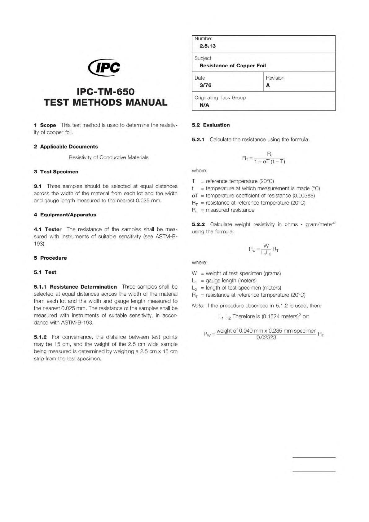
1
Scope
This
test
method
is
used
to
determine
the
resistiv¬
ity
of
copper
foil.
2
Applicable
Documents
Resistivity
of
Conductive
Materials
3
Test
Specimen
3.1
Three
samples
should
be
selected
at
equal
distances
across
the
width
of
the
material
from
each
lot
and
the
width
and
gauge
length
measured
to
the
nearest
0.025
mm.
4
Equipment/Apparatus
4.1
Tester
The
resistance
of
the
samples
shall
be
mea¬
sured
with
instruments
of
suitable
sensitivity
(see
ASTM-B-
193).
5
Procedure
5.1
Test
5.1.1
Resistance
Determination
Three
samples
shall
be
selected
at
equal
distances
across
the
width
of
the
material
from
each
lot
and
the
width
and
gauge
length
measured
to
the
nearest
0.025
mm.
The
resistance
of
the
samples
shall
be
measured
with
instruments
of
suitable
sensitivity,
in
accor¬
dance
with
ASTM-B-193.
5.1.2
For
convenience,
the
distance
between
test
points
may
be
15
cm,
and
the
weight
of
the
2.5
cm
wide
sample
being
measured
is
determined
by
weighing
a
2.5
cm
x
1
5
cm
strip
from
the
test
specimen.
Number
2.5.13
Subject
Resistance
of
Copper
Foil
Date
Revision
3/76
A
Originating
Task
Group
N/A
5.2
Evaluation
5.2.1
Calculate
the
resistance
using
the
formula:
Rt
%
=
1
+
aT
(t
-
T)
where:
T
=
reference
temperature
(20℃)
t
二
temperature
at
which
measurement
is
made
(
℃)
aT
二
temperature
coefficient
of
resistance
(0.00388)
Rt
=
resistance
at
reference
temperature
(20℃)
Rt
=
measured
resistance
5.2.2
Calculate
weight
resistivity
in
ohms
-
gram/meter2
using
the
formula:
Pw
=
^Rt
l1l2
where:
W
二
weight
of
test
specimen
(grams)
L
=
gauge
length
(meters)
L2
二
length
of
test
specimen
(meters)
Rt
=
resistance
at
reference
temperature
(20℃)
Note:
If
the
procedure
described
in
5.1
.2
is
used,
then:
L1
L2
Therefore
is
(0.1524
meters)2
or:
p
weight
of
0.040
mm
x
0.235
mm
specimen
门
where:
where:
NOTE:
Material in this Test Methods Manual was voluntarily established by Technical Committees of the IPC. This material is advisory only
and its use or adaptation is entirely voluntary. IPC disclaims all liability of any kind as to the use, application, or adaptation of this
material. Users are also wholly responsible for protecting themselves against all claims or liabilities for patent infringement.
Equipment referenced is for the convenience of the user and does not imply endorsement by the IPC.
Page 1 of 3
r
ASSOCIATION
CONNECTING
/
ELECTRONICS
INDUSTRIES
221
5
Sanders
Road
Northbrook,
IL
60062-6135
IPC-TM-650
TEST
METHODS
MANUAL
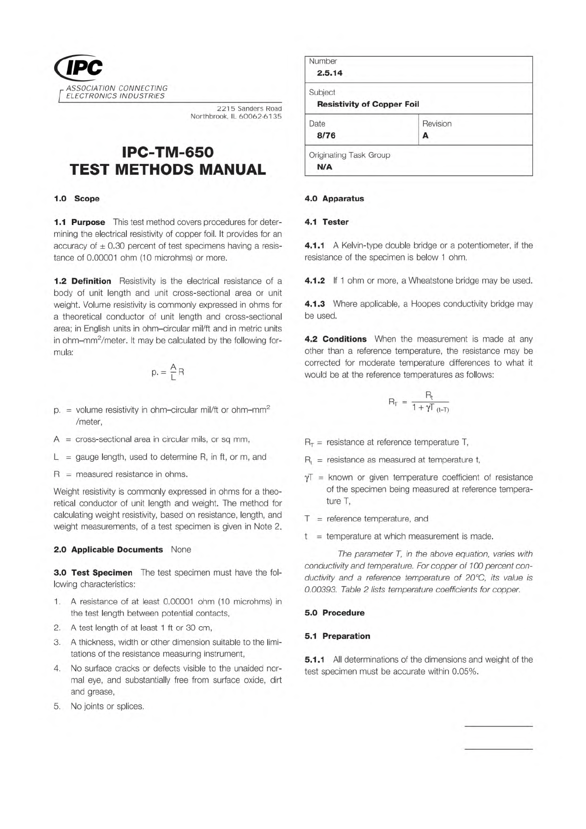
1
.0
Scope
1
.1
Purpose
This
test
method
covers
procedures
for
deter¬
mining
the
electrical
resistivity
of
copper
foil.
It
provides
for
an
accuracy
of
土
0.30
percent
of
test
specimens
having
a
resis¬
tance
of
0.00001
ohm
(10
microhms)
or
more.
1.2
Definition
Resistivity
is
the
electrical
resistance
of
a
body
of
unit
length
and
unit
cross-sectional
area
or
unit
weight.
Volume
resistivity
is
commonly
expressed
in
ohms
for
a
theoretical
conductor
of
unit
length
and
cross-sectional
area;
in
English
units
in
ohm-circular
mil/ft
and
in
metric
units
in
ohm-mm1
2
5/meter.
It
may
be
calculated
by
the
following
for¬
mula:
p.
=
volume
resistivity
in
ohm-circular
mil/ft
or
ohm-mm2
/meter,
A
二
cross-sectional
area
in
circular
mils,
or
sq
mm,
L
=
gauge
length,
used
to
determine
R,
in
ft,
or
m,
and
R
=
measured
resistance
in
ohms.
Weight
resistivity
is
commonly
expressed
in
ohms
for
a
theo¬
retical
conductor
of
unit
length
and
weight.
The
method
for
calculating
weight
resistivity,
based
on
resistance,
length,
and
weight
measurements,
of
a
test
specimen
is
given
in
Note
2.
2
.0
Applicable
Documents
None
3
.0
Test
Specimen
The
test
specimen
must
have
the
fol¬
lowing
characteristics:
1
.
A
resistance
of
at
least
0.00001
ohm
(1
0
microhms)
in
the
test
length
between
potential
contacts,
2.
A
test
length
of
at
least
1
ft
or
30
cm,
3.
A
thickness,
width
or
other
dimension
suitable
to
the
limi¬
tations
of
the
resistance
measuring
instrument,
4.
No
surface
cracks
or
defects
visible
to
the
unaided
nor¬
mal
eye,
and
substantially
free
from
surface
oxide,
dirt
and
grease,
5.
No
joints
or
splices.
Number
2.5.14
Subject
Resistivity
of
Copper
Foil
Date
Revision
8/76
A
Originating
Task
Group
N/A
4.0
Apparatus
4.1
Tester
4.1.1
A
Kelvin-type
double
bridge
or
a
potentiometer,
if
the
resistance
of
the
specimen
is
below
1
ohm,
4.1.2
If
1
ohm
or
more,
a
Wheatstone
bridge
may
be
used.
4.1.3
Where
applicable,
a
Hoopes
conductivity
bridge
may
be
used.
4.2
Conditions
When
the
measurement
is
made
at
any
other
than
a
reference
temperature,
the
resistance
may
be
corrected
for
moderate
temperature
differences
to
what
it
would
be
at
the
reference
temperatures
as
follows:
Rt
Rt
=
3
-
7
-
i
+
丫丁
(t-T)
Rt
=
resistance
at
reference
temperature
T,
Rt
二
resistance
as
measured
at
temperature
t,
yT
=
known
or
given
temperature
coefficient
of
resistance
of
the
specimen
being
measured
at
reference
tempera¬
ture
T,
T
=
reference
temperature,
and
t
二
temperature
at
which
measurement
is
made.
The
parameter
T,
/力
the
above
equation,
varies
with
conductivity
and
temperature.
For
copper
of
100
percent
con¬
ductivity
and
a
reference
temperature
of
20℃,
its
value
0.00393.
Table
2
lists
temperature
coefficients
for
copper.
5.0
Procedure
5.1
Preparation
5.1
.1
All
determinations
of
the
dimensions
and
weight
of
the
test
specimen
must
be
accurate
within
0.05%.
where:
IPC-TM-650
Page 2 of 3
Number
2.5.14
Subject
Resistivity
of
Copper
Foil
Date
8/76
Revision
A
5.1.2
The
cross-sectional
dimensions
of
the
specimen
may
be
determined
by
micrometer
measurements,
and
a
sufficient
number
of
measurements
shall
be
made
to
obtain
the
mean
cross
section
to
within
±
0.10
percent.
5.1.3
In
case
any
dimension
of
the
specimen
is
less
than
0.100
in.
and
cannot
be
measured
to
the
required
accuracy,
the
cross
section
shall
be
determined
from
the
weight,
den¬
sity,
and
length
of
the
specimen.
5.1.4
When
the
density
is
unknown,
it
shall
be
determined
by
weighing
a
specimen
first
in
air
and
then
in
a
liquid
of
known
density
at
the
test
temperature,
which
shall
be
at
room
temperature
to
avoid
errors
due
to
convection
currents.
5.1.5
Calculate
the
density
from
the
following
formula:
WaXd
o
=
Wa-W|
3
=
density
of
the
specimen,
grams
per
cu
cm,
Wa
=
weight
of
the
specimen
in
air,
grams,
W|
=
weight
of
the
specimen
in
the
liquid,
grams,
and
d
二
density
of
the
liquid
at
the
test
temperature,
grams
per
cu
cm.
5.2
Test
5.2.1
When
potential
leads
are
used,
the
distance
between
each
potential
contact
and
the
corresponding
current
contact
shall
be
at
least
equal
to
1-1/2
times
the
cross-sectional
perimeter
of
the
specimen.
5.2.2
The
yoke
resistance
(between
reference
standard
and
test
specimen)
shall
be
appreciably
smaller
than
that
of
either
the
reference
standard
or
the
test
specimen
unless
a
suitable
lead
compensation
method
is
used,
or
it
is
known
that
the
coil
and
lead
ratios
are
sufficiently
balanced
so
that
variation
in
yoke
resistance
will
not
decrease
the
bridge
accuracy
below
stated
requirements.
5.2.3
Make
resistance
measurements
to
an
accuracy
of
±
0.15
percent.
5.2.4
In
all
resistance
measurements,
the
measuring
current
raises
the
temperature
of
the
specimen
above
that
of
the
sur¬
rounding
medium.
Therefore,
care
shall
be
taken
to
keep
the
magnitude
of
the
current
low,
and
the
time
of
its
use
short
enough
so
that
the
change
in
resistance
cannot
be
detected
with
the
galvanometers.
5.2.5
To
eliminate
errors
due
to
contact
potential,
two
read¬
ings,
one
direct
and
one
with
current
reversed,
must
be
taken
in
direct
succession.
5.2.6
Check
tests
are
recommended
whereby
the
specimen
is
turned
end
for
end,
and
the
test
repeated.
5.2.7
Surface
cleaning
of
the
specimen
at
current
and
potential
contact
points
may
be
necessary
to
obtain
good
electrical
contact.
5.3
Evaluation
5.3.1
Reference
Tests
For
reference
tests,
the
report
should
include
the
following:
1
.Identification
of
test
specimen,
2
.Kind
of
material,
3
.Test
temperature,
4
.Test
length
of
specimen,
5
.Method
of
obtaining
cross-sectional
area:
the
average
val¬
ues
of
micrometer
readings,
or,
if
by
weighing
a
record
of
length,
weight,
and
density
determinations
that
may
be
made,
and
calculated
cross-sectional
area.
6
.Weight,
if
used,
7
.Method
of
measuring
resistance,
8
.Value
of
resistance,
9
.
Reference
temperature,
10
.
Calculated
value
of
resistivity
at
the
reference
temperature,
and
1
1
Previous
mechanical
and
thermal
treatments.
(Since
the
resistivity
of
a
material
usually
depends
upon
them,
these
shall
be
stated
whenever
the
information
is
available.
)
5.3.2
Routing
Tests
For
routine
tests,
only
such
of
the
items
in
paragraph
5.3.1
as
apply
to
the
particular
case,
or
are
significant,
shall
be
reported.