IPC-TM-650 EN 2022 试验方法--.pdf - 第528页
Figure 3 Cable Preparation and Cable Connection Figure 4 T est Cable Hookup IPC-TM-650 Number Subject Date Revision Page 3 of 4 2.5.19.1 Propagation Delay of Flat Cables Using Dual Trace Oscilloscope 7/84 A IPC-2-5-19-1-…
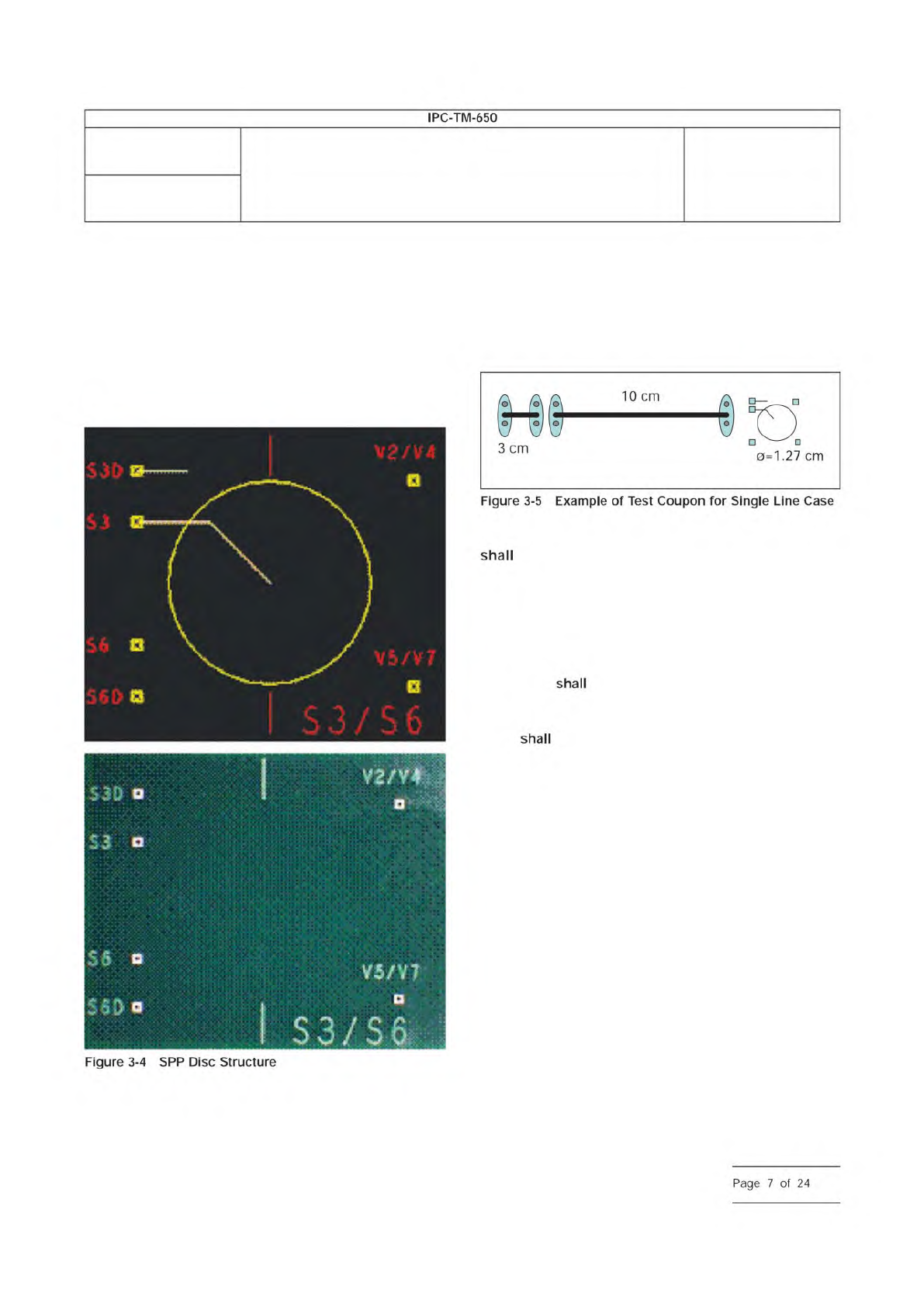
The layout of the disc structure is shown in Figure 3-4. The
red text is on the external surface for pad identification pur-
poses. In a multi-signal layer cross section, disks can be
‘‘stacked’’ vertically to facilitate later cross-sectioning if
desired (e.g., the disc for layer 6 is directly under the disc for
layer 3). The voltage planes around each disc are connected
together at the reference PTH and isolated from the rest of the
test vehicle through the use of a voltage divider.
3.3.4.3 SPP Test Coupon Design
An example is shown of
a typical coupon layout with 3 cm and 10 cm [1.18 in and
3.94 in] long lines and the 12.7 mm [0.5 in] disc in Figure 3-5.
The contacts are shown using the SMA connectors described
in Figure 3-3. This is a minimum configuration. Additional lines
would need to be added for differential line testing. The layout
in Figure 3-5 requires 2.0 cm x 16 cm [0.8 in x 6.3 in] of card
space.
3.3.5 SET2DIL Test Lines
The SET2DIL test coupons
contain one DUT (Device Under Test) for each
impedance/layer combination being controlled, and a ‘‘thru’’
reference structure.
3.3.6 FD Test Lines
The FD test sample shall contain one
transmission (or interconnect) test line per layer. The reference
line shall be between 1.27 cm [0.5 in] and 2.54 cm [1 in].
The test line
be between 15.24 cm [6 in] and 30.49 cm
[12 in]. The recommended line is 1.27 cm [0.5 in] for the ref-
erence line and 20.32 cm [8 in] for the test line. The specific
length be specified by printed board customers or ven-
dors.
3.3.7 Surface Finish
No matter what surface finish is
used, one should ensure the surface of the launch/capture
structure is clean and that the contact of the probes is not
affected by residues and/or oxides. OSP (organic solderability
preservative) finishes may inhibit probing of fine-pitched
probes and may need to be removed from the probe area.
In the lab based qualification/verification assessment, one can
facilitate this by slight burnishing (a pencil eraser often works
well), followed by cleaning with isopropyl alcohol (IPA).
In production floor assessments, the probe design should be
designed to break through any potential oxides or contami-
nants.
4 Apparatus
4.1 Differential and Single Ended Measurements
Both
single ended and differential measurement can be applied to
all the test methods. The measurement process for a differen-
tial measurement is identical to that of a single ended test. For
IPC-25512-3-5
Number
2.5.5.12
Subject
Test Methods to Determine the Amount of Signal Loss on
Printed Boards
Date
07/12
Revision
A
IPC-TM-650
Figure
3-4
SPP
Disc
Structure
shall
shall
shall
Page
7
of
24
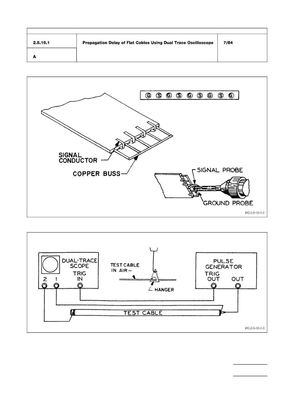
Figure 3 Cable Preparation and Cable Connection
Figure 4 Test Cable Hookup
IPC-TM-650
Number
Subject Date
Revision
Page 3 of 4
2.5.19.1
Propagation
Delay
of
Flat
Cables
Using
Dual
Trace
Oscilloscope
7/84
A
IPC-2-5-19-1-3

Figure 1 Oscilloscope
Figure 2 Connecting Sample
Figure 3 Crosstalk
The Institute for Interconnecting and Packaging Electronic Circuits
2215 Sanders Road • Northbrook, IL 60062
Material in this Test Methods Manual was voluntarily established by Technical Committees of the IPC. This material is advisory only
and its use or adaptation is entirely voluntary. IPC disclaims all liability of any kind as to the use, application, or adaptation of this
material. Users are also wholly responsible for protecting themselves against all claims or liabilities for patent infringement.
Equipment referenced is for the convenience of the user and does not imply endorsement by the IPC.
Page 1 of 2
回
IPC-TM-650
TEST
METHODS
MANUAL
1
Scope
This
test
method
gives
a
procedure
to
determine
crosstalk
or
the
magnitude
of
disturbance
that
is
coupled
to
one
conductor
when
another
conductor
in
a
given
cable
con¬
figuration
is
activated
with
a
pulse.
2
Applicable
Documents
None
3
Test
Specimen
3.1
3.1
m
±
6.4
m
length
of
cable
4
Equipment/Apparatus
4.1
Fast
rise
pulse
generator
4.2
Sampling
plug-in
in
appropriate
oscilloscope
(see
Figure
1)
with
a
high
input
impedance
probe
Q152
m)
GROUND
CONDUCTORS
NOT
SHOWN
I
PC-2-5-21-1
4.3
Test
fixture
to
introduce
signal,
provide
oscilloscope
pickoff
points,
impedance
matching
and
terminating
potenti¬
ometers,
and
a
means
of
connecting
sample
(see
Figure
2)
4.4
Brackets
to
hold
cable
suspended
in
air
and
support
fix¬
ture
close
to
end
of
cable
system
4.5
Styrofoam
with
rigid
backing
for
"stacked”
crosstalk
(see
Figure
3)
4.6
Ohmmeter
5
Procedure
Number
2.5.21
Subject
Digital
Unbalanced
Crosstalk,
Flat
Cable
Date
3/84
Revision
A
Originating
Task
Group
5.1
Setup
5.1.1
Set
pulse
generator
as
follows:
.....
1
megahertz
2
to
5
volts
..
1
nanosecond
2.5
nanosecond
Rep
Rate
...
Pulse
Amp
Pulse
Width
Rise
Time
..