IPC-TM-650 EN 2022 试验方法--.pdf - 第403页
5.3.2 If there is a metal heat spreader on the BGA, it must be left in place until after the dye-drying step (5.11). 5.4 Section out the desired component area l eaving about 19 mm to 38 mm [0.75 in to 1.5 in] of board a…
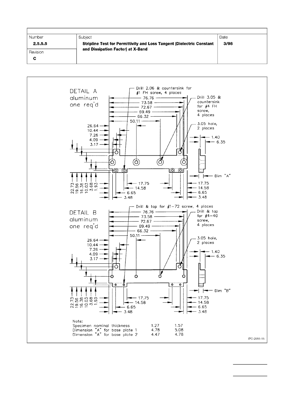
Figure 15 Test Fixture Construction, Older Design
IPC-TM-650
Page 23 of 25
r
50.11
Q
]
0
0
r
Dim
”B”
—
76.76
-
73.58
-
72.67
69.49
-
66.32
-
17.75
14.58
6.65
3.48
3.05
hole,
2
places
Drill
&
tap
for
#4-40
screw,
4
places
Drill
&
tap
for
#1-72
screw,
4
places
17.75
v—
14.58
!■*—
6.65
-
•-
548
—
—
1.40
v
—
6.35
DETAIL
B
aluminum
one
req'd
26.64—
10.44
—
7.26
——
—
4.09
—
3.17
—
Nate:
Specimen
nominal
thickness
1.27
1.57
Dimension
"A"
for
base
plate
1
4.78
5.08
Dimension
"A"
for
base
plate
2
4.47
4.78
©
©
©
K3F
mrn
A
17.75
14.58
17.75
14.58
6.65
3.48
3.05
hole,
2
places
DETAIL
A
aluminum
one
req'd
Drill
3.05
&
countersink
for
#4
FH
screw,
4
places
Drill
2.06
&
countersink
for
#1
FH
screw,
4
places
—
76.76
一
73.58
-
72.67
-
69.49
-
66.32
—
50.11
26.64
10.44
7.26
——
4.09
—
3.17
6.65
3.48
二
及
l)
=K5F
册
1.40
6.35
PC-2555-15
Number
2.5.5.5
Subject
Stripline
Test
for
Permittivity
and
Loss
Tangent
(Dielectric
Constant
and
Dissipation
Factor)
at
X-Band
Date
3/98
Revision
C
r-TTHn
29.0
n
OL
996L
R7Z
5.3.2
If there is a metal heat spreader on the BGA, it must
be left in place until after the dye-drying step (5.11).
5.4
Section out the desired component area leaving about
19 mm to 38 mm [0.75 in to 1.5 in] of board around the part.
If the board is small enough to fit the pull fixture, leave the
board intact.
5.4.1
A diamond sectioning saw is recommended to per-
form this step. Other sectioning equipment (e.g., diamond
saw, milling tool, water jet, etc.) can be used if it does not
induce stress on the sample area.
5.5
A detailed visual examination under stereomicroscope is
required at this stage. If needed, clean the sectioned part with
only water and compressed air. It is important to not use sol-
vent for this step.
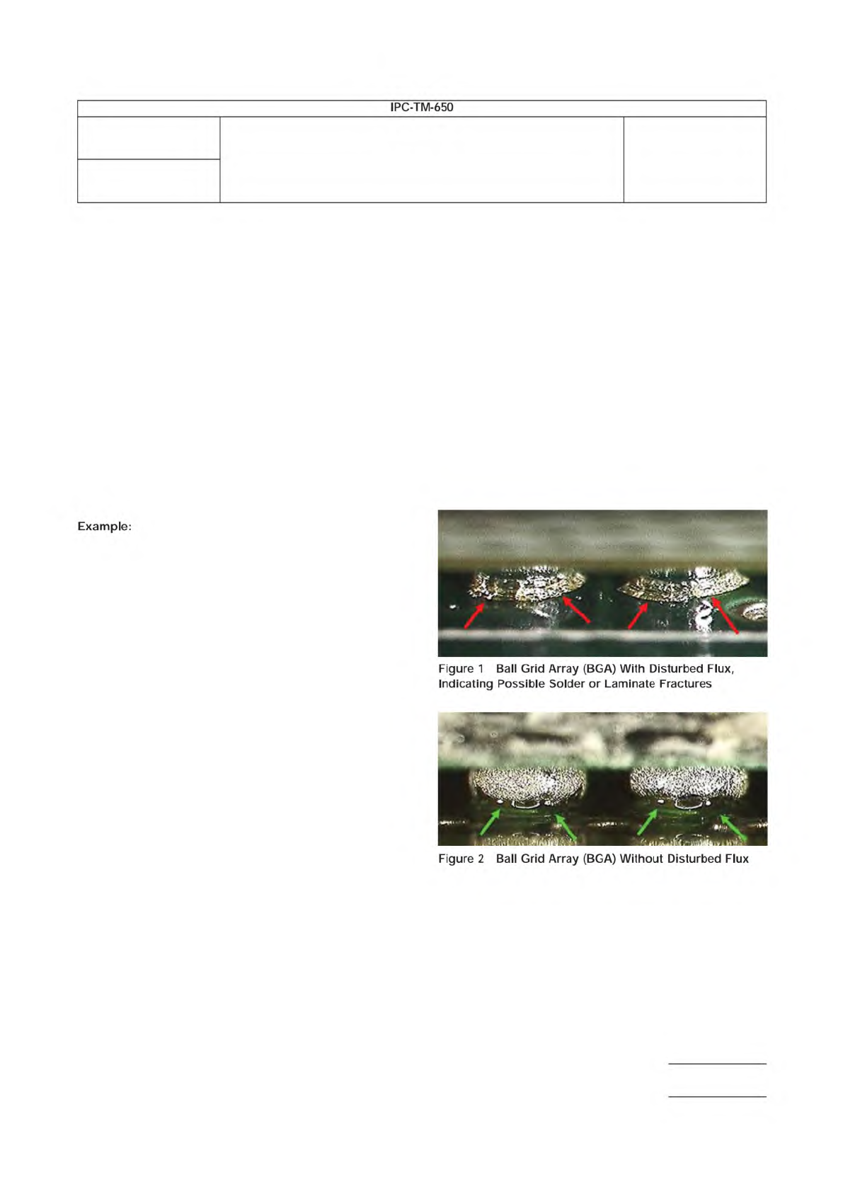
5.5.1
A thorough visual examination can detect signs of
mechanical damage/stress, which are indicated by fractured/
broken-up flux around the SMT solder joint (see Figure 1 and
Figure 2).
5.5.2
If the SMT part utilizes corner-applied adhesive which
was not easily visible before, examine it now. Document the
glue coverage per IPC-7095 or as determined between the
lab and the customer.
5.5.3
Document the findings in lab notes and with photos.
5.6
Clean any flux residue from around the SMT solder joints
using the appropriate flux remover.
Isopropyl alcohol is not acceptable due to its inability to
dissolve flux.
5.6.1
The sectioned part/board area should be submerged
in liquid flux remover for at least one hour. The goal is to fully
remove the flux residue. The exact amount of time the part/
board is submerged depends on the sample conditions.
5.6.1.1
Approximately two to three times during soak, gen-
tly swirl the beaker containing the sectioned part for at least
20 seconds. This will aid the flux solvent in removing the flux
ring residue.
5.6.2
Reworked samples may require additional time in the
liquid flux remover.
5.6.3
Examine the sample under a microscope to determine
if additional time is needed to remove the flux ring.
5.6.4
After using the liquid flux remover, use a spray can flux
remover to thoroughly flush all four sides of the component.
5.6.4.1
Removing all flux residues and other particles/oils
enables the dye to penetrate the fractures.
5.6.4.2
Failure to completely remove the flux from around
the solder joint will prevent dye penetration and give false indi-
cations of a good solder joint.
5.7
Use low-pressure compressed air to blow off excess flux
solvent.
5.7.1
If desired, perform a final rinse with isopropyl alcohol
or acetone at this time.
5.8
Pour the dye into a small tray until the sectioned sample
is completely immersed in the dye.
5.8.1
If dye is being reused, ensure it has sufficient viscos-
ity. Viscosity is critical to the ability of the dye to penetrate into
cracks within the parts being dyed. If there are any concerns
with dye viscosity, discard the old dye and use fresh, new
dye.
5.9
Place the tray containing the sectioned sample into a
vacuum chamber.
5.9.1
Draw a 67.7 kPa [20 in Hg] vacuum for three to four
minutes.
5.9.2
Partially vent and then reapply vacuum to the chamber
to aid in dye penetration.
5.9.3
Leave the part submerged in dye for a minimum of 30
minutes with a constant vacuum of 67.7 kPa [20 in Hg].
5.9.3.1
Do not exceed 67.7 kPa [20 in Hg] of vacuum at any
time, or the dye will start to boil off.
5.10
Vent the vacuum chamber slowly and remove the
sample from the tray.
5.10.1
Allow the excess dye to drain off the sample.
Number
2.4.53
Subject
Dye and Pull Test Method (Formerly Known as Dye and Pry)
Date
8/2017
Revision
Page 2 of 11
IPC-TM-650
Note:
5.10.2
Use low-pressure compressed or canned air to gen-
tly flush any remaining dye from under the part until no further
dye runs out.
5.10.3
Dry the sample in an oven, not to exceed 100 °C or
as appropriate for the sample. If possible, allow the part to dry
overnight at ambient conditions. Wet dye can smear during
component separation, resulting in false conclusions.
5.11
Remove the sectioned part from the oven and allow it
to cool.
5.12
Perform the pull operation to physically/mechanically
remove the part from the board.
5.12.1
Abrade the surface to allow for an improved bonding
of the structural adhesive.
One way to perform this is to use a small piece of
coarse-grit sandpaper to lightly sand and roughen the part top
surface. This will remove the dried dye and will allow the top
surface to bond with the anchored tee nut.
5.12.2
Bond the tee nut to the top of the part using struc-
tural adhesive. Allow the structural adhesive to cure.
5.12.3
Use a pull-test fixture with a uniform tensile force to
separate the part from the board.
5.13
Examine the board and component for dye indications.
If necessary, gently dust with canned air or dry, filtered and
regulated compressed air to the separated part to clear away
pull debris (flakes of dye, solder mask, etc.).
5.13.1
Any fractured interface that was present will be
stained with dye. Usually, both sides are stained in a common
(mirrored) pattern.
5.14
Take photos of dyed regions and plot results as agreed
upon between the lab and the customer.
5.15 Test Report
Include the following (or as agreed upon
between the lab and the customer):
• Initial visual observations (see 5.2 and 5.5)
• Dyed interface separation location
• If required, dye indication amount/percentage (acceptability
criteria to be determined between laboratory and customer)
Other items that can be included in the test report include:
• Mapping of all separation locations
6 Notes/Figures
The figures in this section are included for informational pur-
poses only. They do not depict a correct or incorrect method
for conducting this test method.
Number
2.4.53
Subject
Dye and Pull Test Method (Formerly Known as Dye and Pry)
Date
8/2017
Revision
Page 3 of 11
IPC-TM-650
Example:
Figure
1
Ball
Grid
Array
(BGA)
With
Disturbed
Flux,
Indicating
Possible
Solder
or
Laminate
Fractures
Figure
2
Ball
Grid
Array
(BGA)
Without
Disturbed
Flux