IPC-TM-650 EN 2022 试验方法--.pdf - 第265页
IPC-249-4 Zipper fai lure (also termed Slipstick failure): A peel failure that propagates faster than the crosshead speed and oscillates from the interface between the adhesive layer an d the me tal foil through the cohe…
5.4.4
Repeat steps 5.2.2 through Method B.
5.5 Method E – After Aging Etched Specimen
5.5.1
Prepare Type A etched conductor test specimen in
accordance with Figure 1 using standard commercial prac-
tices per 3.1.1.
5.5.2
Condition specimens for 24 hours at 23 °C ± 2 °C
[73.4 °F ± 3.6 °F] and 50% ± 5% relative humidity. Stabiliza-
tion time may be reduced if statistically sound evidence has
been generated on the specific product line to support the
shorter stabilization times.
5.5.3
Expose each test specimen to five cycles at the time-
temperature sequence: 30 minutes +1/-0 minutes at 150 °C
+5 °C/-0 °C [302 °F +9 °F/-0 °F]; 15 minutes +1/-0 minutes
at 23 °C ± 10 °C [73.4 °F ± 18 °F]; 30 minutes +1/-0 minutes
at -55 °C +0 °C /-5 °C [-67 °F -9 °F/+0 °F]; 15 minutes +1/-0
minutes at 23 °C ± 10 °C [73.4 °F ± 18 °F].
5.5.4
Repeat steps 5.1.2 through 5.1.4 as performed in
Method A.
5.6 Method F – After aging – Die Cut Specimen
5.6.1
Cut Type B test specimens with the Thwing Albert
sample cutter per 3.2.1.
5.6.2
Condition specimens for 24 hours at 23 °C ± 2 °C
(73.4 °F ± 3.6 °F) and 50% ± 5% relative humidity. Stabiliza-
tion time may be reduced if statistically sound evidence has
been generated on the specific product line to support the
shorter stabilization times.
5.6.3
Expose each test specimen to five cycles at the time-
temperature sequence: 30 minutes +1/-0 minutes at 150 °C
+5 °C/-0 °C [302 °F +9 °F/-0 °F]; 15 minutes +1/-0 minutes
at 23 °C ± 10 °C [73.4 °F ± 18 °F]; 30 minutes +1/-0 minutes
at -55 °C +0 °C /-5 °C [-67 °F -9 °F/+0 °F]; 15 minutes +1/-0
minutes at 23 °C ± 10 °C [73.4 °F ± 18 °F].
5.6.4
Repeat steps 5.2.2 through 5.2.4 as performed in
Method B.
5.7 Evaluation
5.7.1
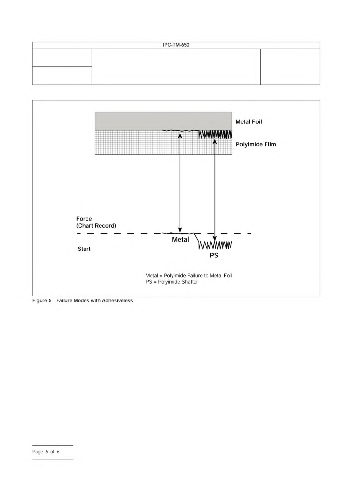
Average the chart recordings for both specimens over
the entire peel length if the mode of failure hasn’t changed. In
the case of changes in failure mode, the average specimen
peel strength
be determined using the area of the chart
associated with the failure modes producing the lowest peel
strength number (see Figures 4 and 5).
5.7.2
Measure and record the width of the etched conduc-
tor or peeled foil to the nearest 0.02 mm [0.001 in].
5.7.3
Compute the peel strength using the following for-
mula: Peel Strength [(metric units first) pounds/in of width] =
Average load per 5.7.1 conductor width per specimen.
6
6.1
The force required to bend the test conductor will affect
the measured peel strength. The magnitude of this effect will
increase as the conductor thickness increases.
6.2
In order to prevent tenting of the peel specimens, suit-
able support material may be applied to the back side of the
test specimen. A referee support material will be a 0.25 mm
[0.010 in] glass epoxy material. Bonding during sample prepa-
ration should occur at conditions not exceeding 65.6 °C
+0 °C/-9 °C [150 °F +0 °F/-16.2 °F] 1 hour cure @ 5171.5 torr
[100 pounds/square in]. In the event of a conflict, a backer will
be used to prevent tenting.
The metal foil on the non-
test side may remain to provide stability to prevent tenting of
the specimen from the German Wheel.
Number
2.4.9
Subject
Peel Strength, Flexible Dielectric Materials
Date
04/14
Revision
E
IPC-TM-650
shall
Notes
Note:
Page
4
of
6
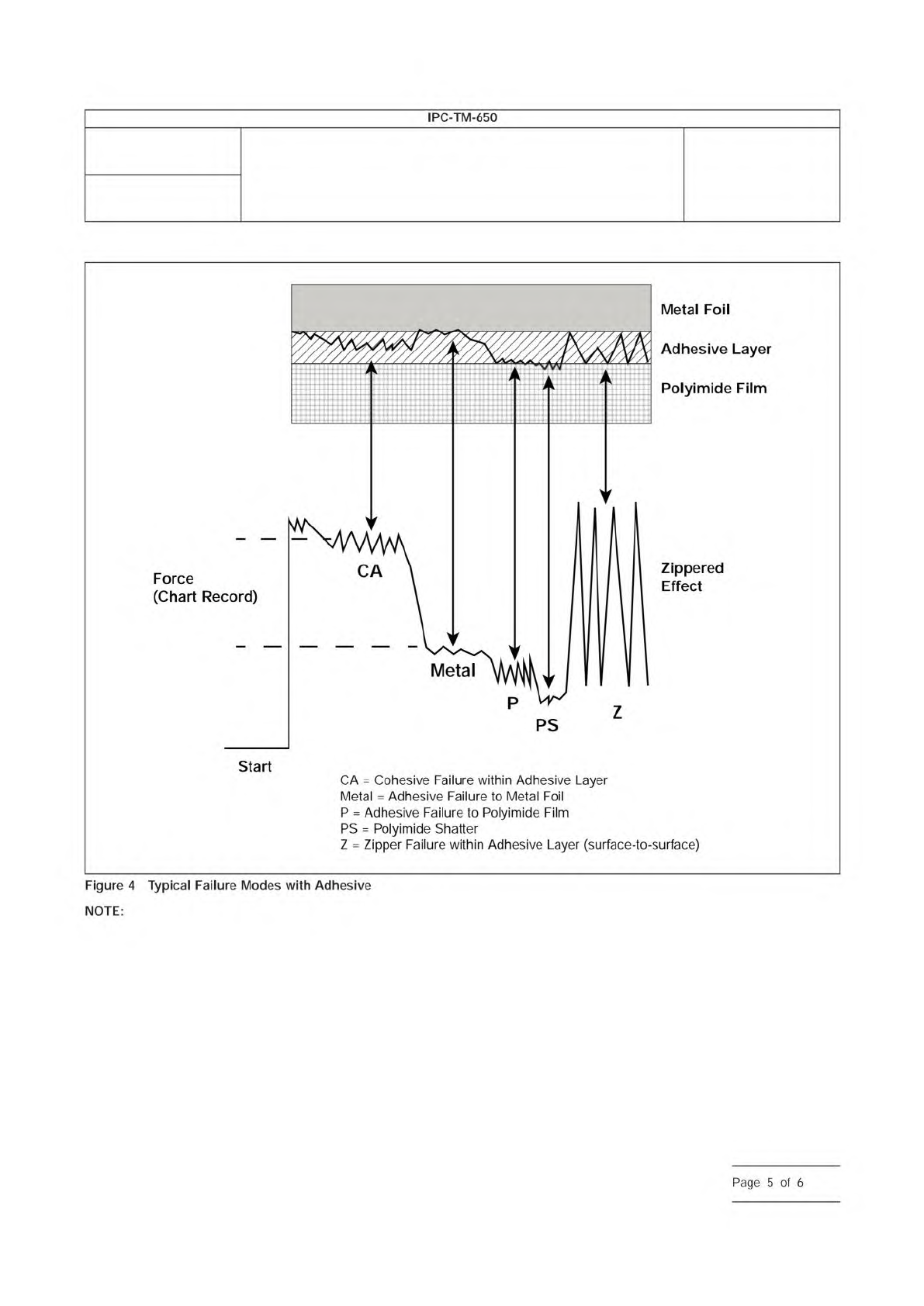
IPC-249-4
Zipper failure (also termed Slipstick failure): A peel failure that propagates faster than the crosshead speed and oscillates from
the interface between the adhesive layer and the metal foil through the cohesive layer of the adhesive itself to the adhesive interface
with the dielectric film and into the dielectric film where it fails cohesively and reverses this failure. It also exhibits itself by peel strengths
that vary widely from a gradual build to a maximum peel value to a nearly instantaneous drop to no peel value at all in a cyclic manner.
Number
2.4.9
Subject
Peel Strength, Flexible Dielectric Materials
Date
04/14
Revision
E
IPC-TM-650
Figure
4
Typical
Failure
Modes
with
Adhesive
NOTE:
Page
5
of
6
IPC-249-5
Number
2.4.9
Subject
Peel Strength, Flexible Dielectric Materials
Date
04/14
Revision
E
IPC-TM-650
—
Metal
=
Polyimide
Failure
to
Metal
Foil
PS
=
Polyimide
Shatter
Figure
5
Failure
Modes
with
Adhesiveless
Page
6
of
6