IPC-TM-650 EN 2022 试验方法--.pdf - 第809页
Note: T a ble 1 T est T em peratures T est Condition Chamber T emperature (°C) T a ble 2 Length of T est T est Time Condition Hours Material in this T est Methods Manual was voluntarily established by T echnical Committe…
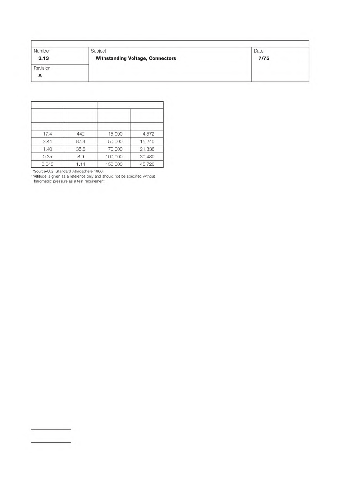
Table 1
Barometric Pressure* Altitude**
In. of
Mercury
MM of
Mercury Feet Meters
27 to 31 685 to 785 Seal Level Seal Level
IPC-TM-650
Page 2 of 2
Number
3.13
Subject
Withstanding
Voltage,
Connectors
Date
7/75
Revision
A
*Source-U.S.
Standard
Atmosphere
1966.
**Altitude
is
given
as
a
reference
only
and
should
not
be
specified
without
barometric
pressure
as
a
test
requirement.
17.4
442
15,000
4,572
3.44
87.4
50,000
15,240
1.40
35.6
70,000
21,336
0.35
8.9
100,000
30,480
0.045
1.14
150,000
45,720
Note:
Table 1 Test Temperatures
Test Condition Chamber Temperature (°C)
Table 2 Length of Test
Test Time Condition Hours
Material in this Test Methods Manual was voluntarily established by Technical Committees of the IPC. This material is advisory only
and its use or adaptation is entirely voluntary. IPC disclaims all liability of any kind as to the use, application, or adaptation of this
material. Users are also wholly responsible for protecting themselves against all claims or liabilities for patent infringement.
Equipment referenced is for the convenience of the user and does not imply endorsement by the IPC.
Page 1 of 2
Number
3.14
r
ASSOCIATION
CONNECTING
/
ELECTRONICS
INDUSTRIES
2215
Sanders
Road
Northbrook,
IL
60062-6135
IPC-TM-650
TEST
METHODS
MANUAL
1
Scope
This
test
method
is
used
to
determine
the
effects
of
exposure
to
elevated
ambient
temperature
on
the
electrical
and
mechanical
characteristics
of
a
connector.
2
Applicable
Documents
None
3
Test
Specimen
3.1
A
mated
connector
(plug
and
receptacle)
complete
with
all
applicable
guide,
keying,
and
engaging
hardware
shall
be
terminated
and
mounted
in
its
normal
manner
during
this
test.
3.2
The
card-edge
receptacle
and
an
applicable
PCB
of
minimum
thickness
shall
be
mated
during
this
test,
except
as
otherwise
specified.
4
Equipment/Apparatus
4.1
A
suitable
chamber
capable
of
maintaining
the
appli¬
cable
temperatures
within
±
20℃
at
the
geometric
center
under
no
load
conditions.
Thermal
distribution
shall
not
exceed
±
50℃
of
the
temperature
at
the
geometric
center.
4.2
A
thermocouple
bridge,
potentiometer,
or
resistance
bridge
of
suitable
range
for
the
specified
test
conditions
5
Procedure
5.1
The
chamber
shall
be
adjusted
to,
and
maintained
at,
the
temperature
specified
in
the
individual
connector
specifi¬
cation.
Thermal
equilibrium
shall
be
attained
prior
to
the
start
of
the
test
(see
6.3).
5.2
The
mated
test
specimen
shall
be
suspended
within
the
test
chamber
and
subjected
to
the
specified
temperature
for
the
required
time
duration
called
out
in
the
individual
specifi¬
cation.
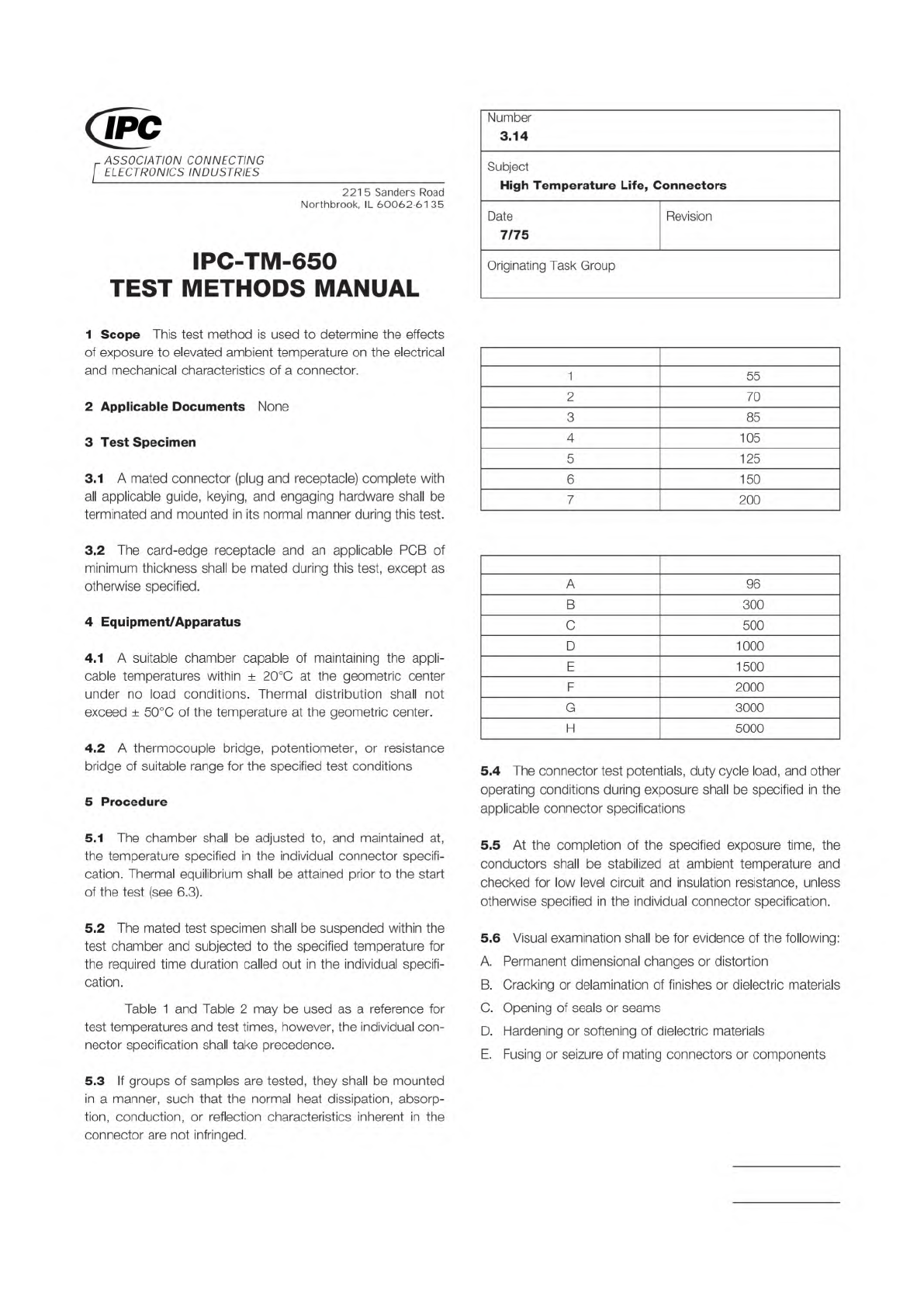
Table
1
and
Table
2
may
be
used
as
a
reference
for
test
temperatures
and
test
times,
however,
the
individual
con¬
nector
specification
shall
take
precedence.
5.3
If
groups
of
samples
are
tested,
they
shall
be
mounted
in
a
manner,
such
that
the
normal
heat
dissipation,
absorp¬
tion,
conduction,
or
reflection
characteristics
inherent
in
the
connector
are
not
infringed.
Subject
High
Temperature
Life,
Connectors
Date
7/75
Revision
Originating
Task
Group
1
55
2
70
3
85
4
105
5
125
6
150
7
200
A
96
B
300
C
500
D
1000
E
1500
F
2000
G
3000
H
5000
5.4
The
connector
test
potentials,
duty
cycle
load,
and
other
operating
conditions
during
exposure
shall
be
specified
in
the
applicable
connector
specifications
5.5
At
the
completion
of
the
specified
exposure
time,
the
conductors
shall
be
stabilized
at
ambient
temperature
and
checked
for
low
level
circuit
and
insulation
resistance,
unless
otherwise
specified
in
the
individual
connector
specification.
5.6
Visual
examination
shall
be
for
evidence
of
the
following:
A.
Permanent
dimensional
changes
or
distortion
B.
Cracking
or
delamination
of
finishes
or
dielectric
materials
C.
Opening
of
seals
or
seams
D.
Hardening
or
softening
of
dielectric
materials
E.
Fusing
or
seizure
of
mating
connectors
or
components
IPC-TM-650
Page 2 of 2
Number
3.14
Revision
Subject
High
Temperature
Life,
Connectors
Date
7/75
6
Notes
6.1
Acceptance
criteria
shall
be
established
in
terms
of
one
or
any
combination
of
the
following:
A.
Visible
evidence
of
damage
or
significant
material
change
B.
Deterioration
of
low
level
circuit
or
insulation
resistance
beyond
allowable
specified
limits,
or
other
requirements
called
out
in
an
individual
specification
6.2
The
test
chambers
shall
be
of
the
forced-
(circulating)
air
type
to
ensure
temperature
distribution.
6.3
Thermal
equilibrium
shall
be
assumed,
when
three
suc¬
cessive
thermocouple
readings
taken
at
five-minute
intervals
indicate
variations
of
30℃
or
less.
6.4
Information
in
this
test
method
is
intended
to
parallel
the
test
method
described
in
EIA-RS-364ATP-1
7.