IPC-TM-650 EN 2022 试验方法--.pdf - 第693页
• D uring the initial c ycle after t he high temperature dwell. Peak r e s i s t a n c e d u r i n g t h i s c y c l e b e th e r e f e r e n c e resistance. • A t or near the end of the peak temperature dwell, after the…

4.1.4
Deviations to the test specimen design/construction
or use of an alternate test specimen
be AABUS.
5 Apparatus
5.1 Drying Oven
The oven be capable of maintaining
a uniform set temperature within the 105 to 125 °C range.
5.2
Environmental Test Chamber
5.2.1 Dual Chamber Option
An automatically controlled
dual temperature environmental test chamber or other
apparatus capable of maintaining the upper and lower
temperatures.
5.2.2 Single Chamber Option
An automatically controlled
environmental test chamber or other apparatus capable of
maintaining the upper and lower temperatures.
5.2.3
The system have adequate environmental con-
trols to maintain the tolerance range and limits listed in
6.5.1.3.
5.2.4
The system should accommodate verifiable calibration
compliance. See note 7.1 for additional considerations.
5.2.5
Deviations to the equipment requirements and
acceptability of the alternative methods
be AABUS.
5.3 Microscope
The magnification used for defect recogni-
tion
be in agreement with the inspection requirements/
capabilities defined in the applicable performance specifica-
tion (e.g., IPC-6012, IPC-6013, IPC-6018, etc.) and the IPC-
A-600 visual workmanship standard.
5.4 Resistance Measurements
5.4.1
The resistance measurement have enough pre-
cision to clearly determine the resistance percent change as
required by the user for the resistance level of each test speci-
men’s nets.
5.4.2
The total system uncertainty from resistance, tem-
perature and time/cycle variations
be less than 10% of
the failure criteria required by the user. For example, if the
required failure criteria is 5% then the total system uncertainty
be no greater than 0.50%.
5.4.3
The resistance measurement system be capable
of recording resistances at least once per cycle, at or near the
end of the peak temperature dwell, after the coupon has
reached temperature stabilization.
5.5 Temperature Measurements
5.5.1
The temperature measurement system should be
capable of recording temperatures at least once per second
throughout a complete cycle for both a representative test
specimen and the heating/cooling medium. The system
be capable of demonstrating the change rate defined in 3.1
and 3.2 and documenting a representative cycle.
6 Procedure
6.1 Conditioning
6.1.1
The test specimen(s) be conditioned by drying in
an oven to remove moisture for a minimum of six (6) hours at
105 to 125 °C. This conditioning process is mandatory if this
method is used for qualification purposes.
This method
replicate the assembly process. The
requirement for conditioning (bake/drying)
be in accor-
dance with product/process lot Quality Conformance criteria.
If conditioning of the printed board is not part of the normal
assembly process, and this method is being used for quality
conformance testing, then conditioning is not a requirement.
6.1.2
Test specimens that are thicker or more complex may
require longer baking times to achieve acceptable moisture
levels. Record the bake times and temperature if different than
those stated in 6.1.1. See IPC-1602 for additional guidance
on baking to achieve acceptable moisture levels.
6.1.3
Deviations to the conditioning requirements in 6.1.1
such as when used for quality conformance criteria and/or any
changes to the time and temperature
be AABUS.
6.2 Reflow Simulation
6.2.1
The test specimen(s) be subjected to six (6)
reflow simulation cycles in accordance with IPC-TM-650,
Method 2.6.27 prior to Thermal Shock or Thermal Cycling.
6.2.2
The reflow profile be in accordance with IPC-
TM-650, Method 2.6.27, as specified.
6.2.3
Other profiles or reflow simulation testing for other
than 6 cycles are AABUS.
6.3 Interconnect Resistance Measurements
Intercon-
nect resistance measurements
be taken at the following
times:
• Prior to the test (initial ambient after reflow simulation).
Number
2.6.7.2
Subject
Thermal Shock, Thermal Cycle and Continuity
Date
3/2020
Revision
C
IPC-TM-650
—
shall
shall
shall
shall
shall
shall
shall
shall
shall
shall
shall
shall
shall
shall
shall
shall
Page
2
of
5
• During the initial cycle after the high temperature dwell. Peak
resistance during this cycle
be the reference
resistance.
• At or near the end of the peak temperature dwell, after the
coupon has reached temperature stabilization, peak resis-
tance during the cycle
be recorded.
6.4 Qualification (also see 6.6 and Table 6-2)
For quali-
fication testing, the product environment and life expectancy
should be taken into consideration to determine the tempera-
ture extremes and number of cycles. Qualification testing
parameters
be AABUS.
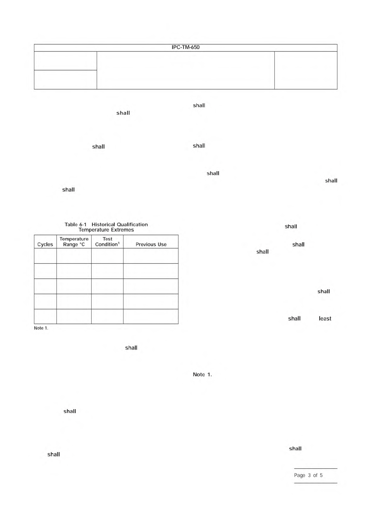
6.4.1 Historical Examples
Historical examples as
described in Table 6-1 were not product focused.
6.4.2 Cycles
The test specimen(s) be subjected to
the specified number of cycles between the specified tem-
perature extremes.
6.4.2.1 Tolerances
The tolerance associated with the hot
cycle is +/-5 °C. The tolerance associated with the cold cycle
is +/-5 °C.
6.4.3 Dwell Time at Extremes
During each cycle, the test
specimen(s)
be subjected to each temperature extreme
for the time required for stabilization and resistance measure-
ment (15 minutes when a dual chamber is used).
6.4.4 Temperature Change Rate
The rate of change
between temperature extremes, both high to low and low to
high,
be as high as possible. The temperature change
be at least 10 °C per minute for at least the center 60%
of each transition period, hot to cold and cold to hot.
6.4.5 Temperature Documentation
6.4.5.1
The temperature of a representative test specimen
be recorded at the end of the dwell at each temperature
extreme, for every cycle.
6.4.5.2
A temperature profile from at least one complete
cycle
be recorded during each test in accordance with
5.5.1 and 6.4.2.1 and included in the test report. This
include the temperatures of a representative test specimen
and the hot/cold media. Recording data every second for this
purpose is recommended.
6.4.6 Dual Chamber Systems
For dual chamber systems:
• The transfer time between chambers
be less than two
(2) minutes.
• The thermal capacity of each chamber
be such that
the ambient temperature
reach the specified tempera-
ture within two (2) minutes after the test specimens have
been transferred to the appropriate chamber.
6.5 Quality Conformance (see also 6.6 and Table 6-2)
6.5.1 Temperature Cycling
The test specimen(s) be
subjected to one hundred (100) cycles of temperature cycling
to the extremes defined below:
6.5.1.1
The high temperature extreme be the of
the following:
• Material T
g
1
– 10 °C (lowest T
g
of the materials used in the
specimen, but not lower than 125 °C)
• Reflow peak temperature – 25 °C
• 210 °C
The originating subcommittee for this Test Method
was not able to obtain industry consensus on a default
method for determining T
g
. Therefore, methods to determine
T
g
(as specified in the procurement documentation or AABUS)
may include:
• Lowest T
g
listed on the Material Data Sheet
• T
g
(from TMA) listed on the Specification Slash sheet
• Actual T
g
of the material, determined after reflow simulation
6.5.1.2
The low temperature extreme be one of the
following:
100 -40 to +85 B
Generic for IPC-4103,
RT/duroid® materials
100 -55 to +105 C
Generic for IPC-4101,
G10 materials
100 -55 to +125 D
Generic for IPC-4101,
Epoxy materials
100 -65 to +150 E
Generic for IPC-4101,
FR-5 materials
100 -65 to +170 F
Generic for IPC-4101,
Polyimide materials
Test Conditions B through F are from the previous revision to this
test method.
Number
2.6.7.2
Subject
Thermal Shock, Thermal Cycle and Continuity
Date
3/2020
Revision
C
IPC-TM-650
—
shall
shall
shall
shall
shall
shall
shall
Table
6-1
Historical
Qualification
Temperature
Extremes
Note
1.
Cycles
Temperature
Range
Test
Condition1
Previous
Use
shall
shall
shall
shall
shall
shall
least
Note
1.
shall
shall
Page
3
of
5
• -40 °C
• -55 °C (default)
• -65 °C
6.5.1.3 Tolerances
The tolerance associated with the hot
cycle is +/-5 °C. The tolerance associated with the cold cycle
is +/-5 °C.
6.5.1.4 Dwell Time at Extremes
During each cycle, the
test specimen(s)
be subjected to each temperature
extreme for the time required for stabilization plus time
required to record all measurements (up to 15 minutes when
a dual chamber is used).
6.5.2 Temperature Change Rate
The rate of change
between temperature extremes, both high to low and low to
high,
be as high as possible. The temperature change
be at least 1 °C per second for at least the center 60%
of each transition period, hot to cold and cold to hot. Note
that for thicker coupons greater than 2.5 mm [0.100 in], this
change rate may not be achievable.
6.5.2.1 Temperature Documentation
6.5.2.1.1
The temperature of a representative test speci-
men
be recorded at the end of the dwell at each tem-
perature extreme, for every cycle.
6.5.2.1.2
A temperature profile from at least one complete
cycle
be recorded during each test and included in the
test report. This
include the temperatures of a
representative test specimen and the hot/cold media. The
temperatures
be taken at sufficient frequency to show
compliance to 5.5.1 and 6.5.1.3. Recording data every sec-
ond for this purpose is recommended.
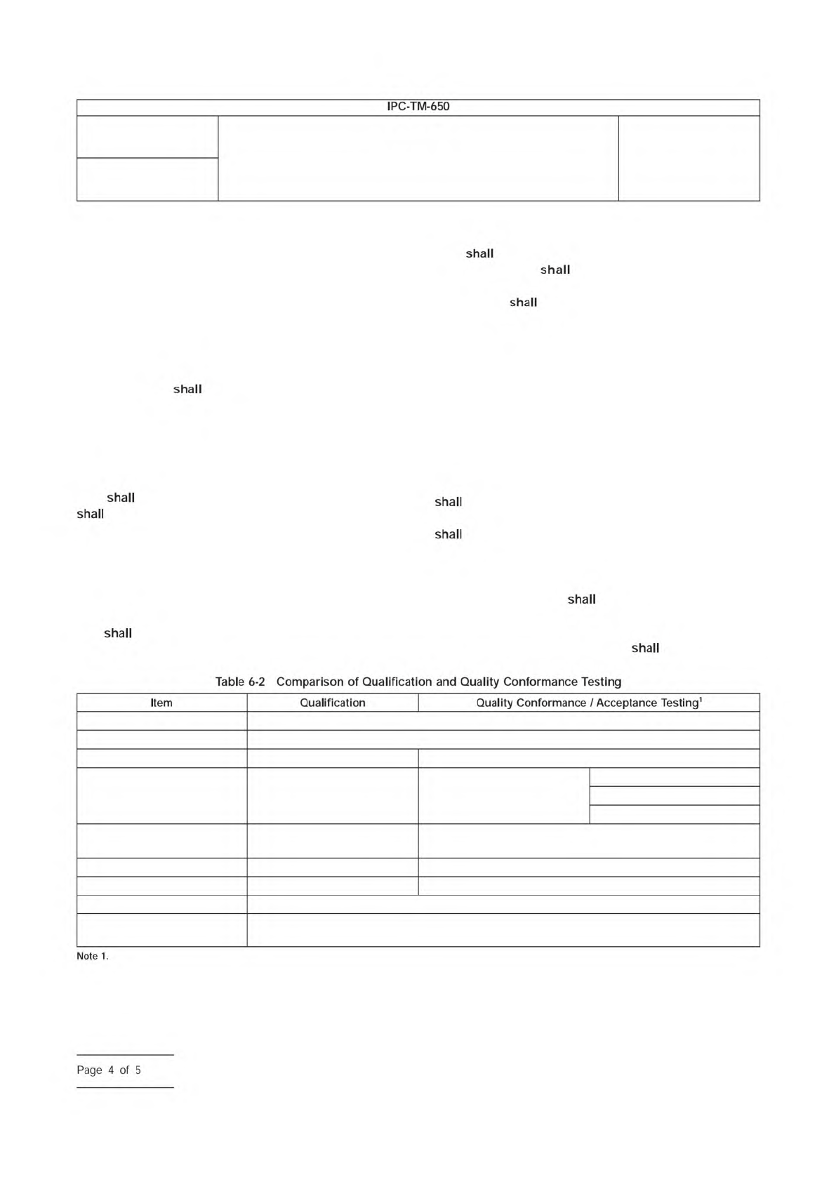
6.6 Testing Summary
A summary of Qualification and Quality Conformance testing
is listed below in Table 6-2.
6.7 Evaluation
6.7.1 Resistance Change
The change in resistance
between the first and each succeeding temperature cycle
be determined. The maximum allowable percent change
in resistance between the first and any subsequent cycle
be 5% unless otherwise specified.
6.7.2 Results
Test results including cycles to failure, corre-
sponding percent change of the failure, and the percent
change of the final cycle
be documented.
6.8 Deviations
Deviations to the stated requirements or
additional requirements defined here
be AABUS.
Conditioning 6 hours minimum, 105 - 125 °C
Reflow Simulation 6 cycles, 230, 245 or 260 °C profile
Temperature Min AABUS -40 °C, -55 °C (default), -65 °C
Temperature Max AABUS min. of:
T
g
-10 °C
Reflow peak -25 °C
210 °C
Sample Change Rate
> 10 °C/min for both hot and
cold
> 1 °C/sec for both hot and cold
Number of Cycles AABUS 100
Failure Threshold AABUS 5%
Resistance Data 1 reading/cycle near the end of the high temperature dwell
Temperature Data
1 reading/cycle near the end of the high and low temperature dwells (sample)
1 reading/sec through 1 complete cycle (sample and media)
Acceptance testing and quality conformance testing as described in IPC-6010 series printed board performance specifications.
Number
2.6.7.2
Subject
Thermal Shock, Thermal Cycle and Continuity
Date
3/2020
Revision
C
IPC-TM-650
shall
shall
shall
shall
shall
shall
shall
shall
shall
shall
shall
Table
6-2
Comparison
of
Qualification
and
Quality
Conformance
Testing
Note
1.
Item
Qualification
Quality
Conformance
/
Acceptance
Testing1
—
Page
4
of
5