IPC-TM-650 EN 2022 试验方法--.pdf - 第487页
ASTM D229 ASTM D149 The Institute for Int erconnecting and Packaging E lectronic Circuits 2215 Sanders Road • Northbrook, IL 60062 Material in this T est M ethods Manual was vol untaril y establis hed by T echni cal Comm…
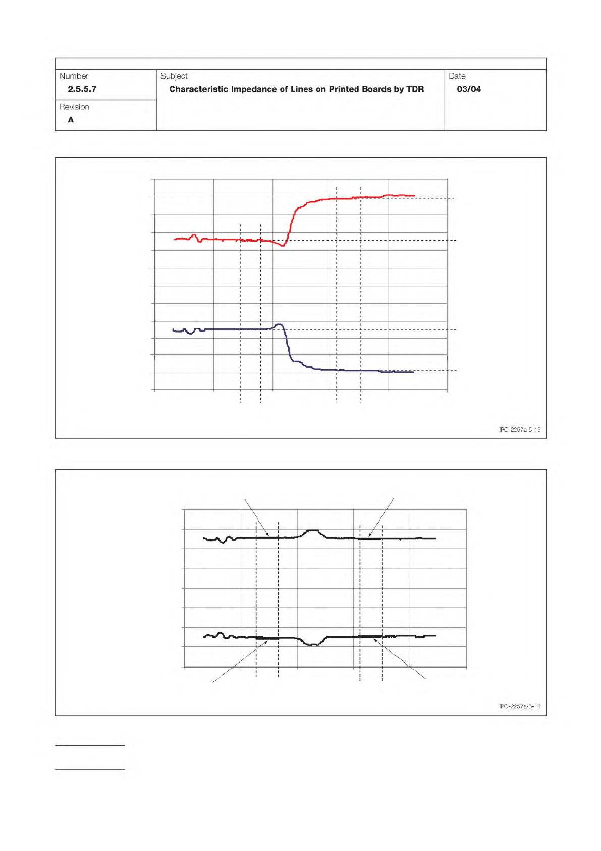
Figure 5-15 Measuring Amplitude for Incident Step
-0.4
-0.3
-0.2
-0.1
0.0
0.1
0.2
0.3
0.4
Signal (V)
Time
t
i,TS
t
f,TS
V
open,Ch1
V
open,Ch
2
Ch1
Ch2
V
TS,Ch2,1
V
TS,Ch1,1
-0.5
-0.6
t
i,TL
t
f,TL
0.5
0.6
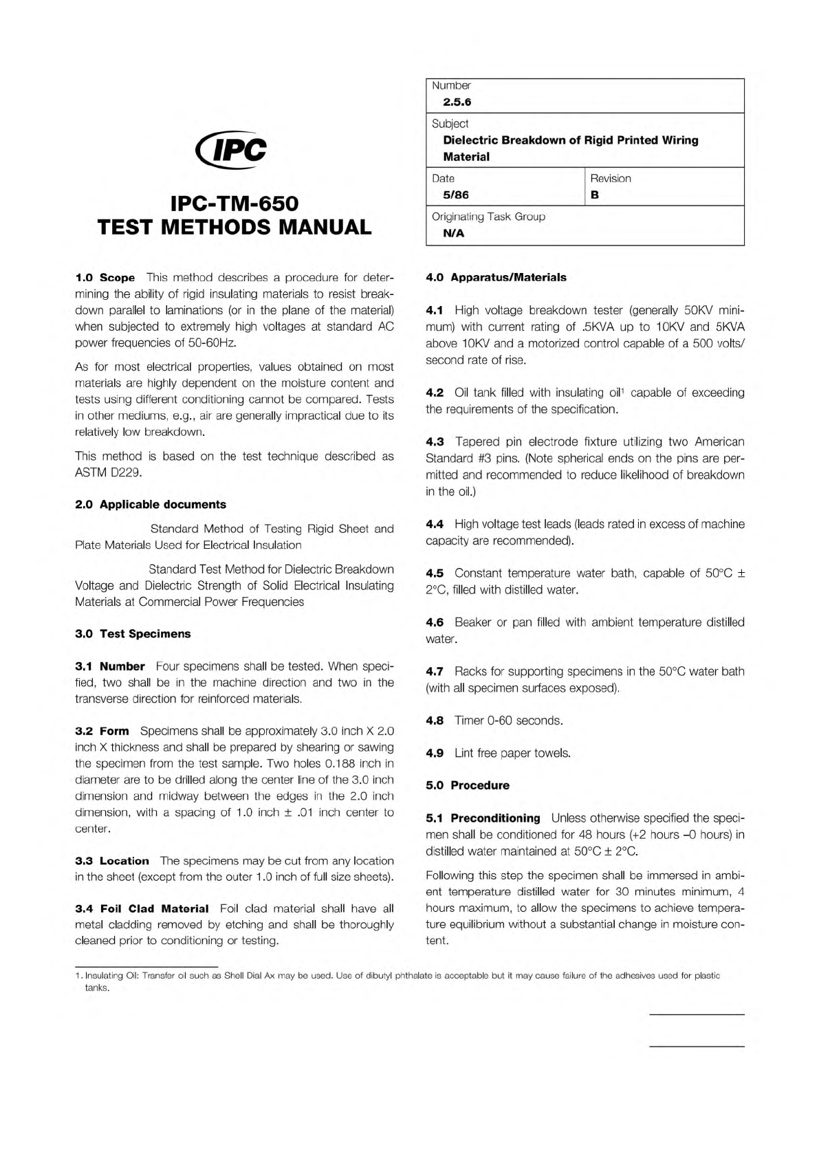
Figure 5-16 Calibration of Transfer Standard
-0.4
-0.3
-0.2
-0.1
0.0
0.1
0.2
0.3
0.4
Signal (V)
Time
V
TS,Ch2,2
V
TS,Ch1,2
t
i,TS
t
i,std
t
f,std
t
f,TS
Ch1
Ch2
V
std,Ch1
V
std,Ch2
IPC-TM-650
Page 18 of 23
Number
2.5.5.7
Subject
Characteristic
Impedance
of
Lines
on
Printed
Boards
by
TDR
Date
03/04
Revision
A
IPC-2257a-5-16
ASTM D229
ASTM D149
The Institute for Interconnecting and Packaging Electronic Circuits
2215 Sanders Road • Northbrook, IL 60062
Material in this Test Methods Manual was voluntarily established by Technical Committees of the IPC. This material is advisory only
and its use or adaptation is entirely voluntary. IPC disclaims all liability of any kind as to the use, application, or adaptation of this
material. Users are also wholly responsible for protecting themselves against all claims or liabilities for patent infringement.
Equipment referenced is for the convenience of the user and does not imply endorsement by the IPC.
Page 1 of 3
IPC-TM-650
TEST
METHODS
MANUAL
Number
2.5.6
Subject
Dielectric
Breakdown
of
Rigid
Printed
Wiring
Material
Date
Revision
5/86
B
Originating
Task
Group
N/A
1
.0
Scope
This
method
describes
a
procedure
for
deter¬
mining
the
ability
of
rigid
insulating
materials
to
resist
break¬
down
parallel
to
laminations
(or
in
the
plane
of
the
material)
when
subjected
to
extremely
high
voltages
at
standard
AC
power
frequencies
of
50-60Hz.
As
for
most
electrical
properties,
values
obtained
on
most
materials
are
highly
dependent
on
the
moisture
content
and
tests
using
different
conditioning
cannot
be
compared.
Tests
in
other
mediums,
e.g.,
air
are
generally
impractical
due
to
its
relatively
low
breakdown.
This
method
is
based
on
the
test
technique
described
as
ASTM
D229.
2
.0
Applicable
documents
Standard
Method
of
Testing
Rigid
Sheet
and
Plate
Materials
Used
for
Electrical
Insulation
Standard
Test
Method
for
Dielectric
Breakdown
Voltage
and
Dielectric
Strength
of
Solid
Electrical
Insulating
Materials
at
Commercial
Power
Frequencies
3
.0
Test
Specimens
3.1
Number
Four
specimens
shall
be
tested.
When
speci¬
fied,
two
shall
be
in
the
machine
direction
and
two
in
the
transverse
direction
for
reinforced
materials.
3.2
Form
Specimens
shall
be
approximately
3.0
inch
X
2.0
inch
X
thickness
and
shall
be
prepared
by
shearing
or
sawing
the
specimen
from
the
test
sample.
Two
holes
0.188
inch
in
diameter
are
to
be
drilled
along
the
center
line
of
the
3.0
inch
dimension
and
midway
between
the
edges
in
the
2.0
inch
dimension,
with
a
spacing
of
1
.0
inch
±
.01
inch
center
to
center.
3.3
Location
The
specimens
may
be
cut
from
any
location
in
the
sheet
(except
from
the
outer
1.0
inch
of
full
size
sheets).
3.4
Foil
Clad
Material
Foil
clad
material
shall
have
all
metal
cladding
removed
by
etching
and
shall
be
thoroughly
cleaned
prior
to
conditioning
or
testing.
4.0
Apparatus/Materials
4.1
High
voltage
breakdown
tester
(generally
50KV
mini¬
mum)
with
current
rating
of
.5KVA
up
to
10KV
and
5
KVA
above
1
0KV
and
a
motorized
control
capable
of
a
500
volts/
second
rate
of
rise.
4.2
Oil
tank
filled
with
insulating
oil1
capable
of
exceeding
the
requirements
of
the
specification.
4.3
Tapered
pin
electrode
fixture
utilizing
two
American
Standard
#3
pins.
(Note
spherical
ends
on
the
pins
are
per¬
mitted
and
recommended
to
reduce
likelihood
of
breakdown
in
the
oil.)
4.4
High
voltage
test
leads
(leads
rated
in
excess
of
machine
capacity
are
recommended).
4.5
Constant
temperature
water
bath,
capable
of
50℃
±
2
℃,
filled
with
distilled
water.
4.6
Beaker
or
pan
filled
with
ambient
temperature
distilled
water.
4.7
Racks
for
supporting
specimens
in
the
50℃
water
bath
(with
all
specimen
surfaces
exposed).
4.8
Timer
0-60
seconds.
4.9
Lint
free
paper
towels.
5.0
Procedure
5.1
Preconditioning
Unless
otherwise
specified
the
speci¬
men
shall
be
conditioned
for
48
hours
(+2
hours
-0
hours)
in
distilled
water
maintained
at
50℃
±
2
℃.
Following
this
step
the
specimen
shall
be
immersed
in
ambi¬
ent
temperature
distilled
water
for
30
minutes
minimum,
4
hours
maximum,
to
allow
the
specimens
to
achieve
tempera¬
ture
equilibrium
without
a
substantial
change
in
moisture
con¬
tent.
1
.
Insulating
Oil:
Transfer
oil
such
as
Shell
Dial
Ax
may
be
used.
Use
of
dibutyl
phthalate
is
acceptable
but
it
may
cause
failure
of
the
adhesives
used
for
plastic
tanks.
Note:
Note:
Note:
Table 1 Voltage increments for Step by Step Test
Breakdown Voltage (KV) Increment KV
less than 12.5 0.5
over 12.5 to 25 1.0
over 25 to 50 2.5
over 50 to 100 5
over 100 10
IPC-TM-650
Number
Subject Date
Revision
Page 2 of 3
2.5.6
Dielectric
Breakdown
of
Rigid
Printed
Wiring
Material
5/86
B
5.2
Test
Condition
The
test
shall
be
performed
at
ambient
temperature
(23℃
±
5
℃).
Relative
humidity
is
not
significant
as
the
tests
are
performed
under
oil.
5.3
Equipment
Set
Up
5.3.1
Adjust
the
transformer
on
the
high
voltage
tester
(manually
for
most
models)
to
the
position
which
will
allow
for
the
necessary
voltage
to
be
achieved
with
adequate
current
capacity
for
breakdown.
5.3.2
Set
the
machine
for
testing
using
a
500
volt
per
sec¬
ond
rate
of
rise.
5.4
Test
5.4.1
Remove
a
preconditioned
specimen
from
the
ambient
temperature
water
and
wipe
dry
with
a
lint
free
paper
towel.
5.4.2
Insert
the
first
specimen
into
the
fixture
(inserting
the
tapered
pins
from
opposite
sides)
and
immerse
in
the
oil
bath.
5.4.3
Attach
leads
(if
not
permanently
wired)
so
that
one
high
voltage
lead
is
connected
to
one
tapered
pin
electrode
and
the
ground
lead
is
connected
to
the
other
tapered
pin
electrode.
5.4.4
Operate
the
tester
such
that
the
voltage
is
applied
with
a
500
volts
per
second
rate
of
rise
and
observe
the
specimen
until
an
electrical
breakdown
occurs.
5.4.5
Record
the
voltage
at
which
breakdown
occurs,
using
the
meter
memory
device
if
available.
If
the
breakdown
appears
to
be
in
the
oil
and
no
specimen
damage
is
obvious
it
is
recommended
that
the
same
sample
be
retested.
If
the
specimen
still
will
not
breakdown
due
to
breakdown
of
the
oil,
the
oil
should
be
filtered
or
replaced.
5.4.6
Determine
the
starting
voltage
and
steps
for
the
remaining
specimens
from
the
same
sample
from
Table
1
.
547
Change
the
high
voltage
tester
to
manual
(or
pro¬
grammed
stepped)
operation,
remove
a
specimen
from
the
water
bath,
wipe
dry,
and
insert
the
second
specimen.
5.4.8
Set
the
voltage
to
the
50%
value
(plus
or
minus
the
value
of
one
step)
and
apply
the
voltage
for
60
seconds.
5.4.9
If
no
breakdown
occurs
increase
the
voltage
in
steps
per
Table
1
until
the
material
breaks
down
or
the
breakdown
capacity
of
the
machine
or
oil
is
reached.
Record
the
break¬
down
voltage
to
the
nearest
kilovolt
or
record
"N.
B.''
if
there
is
no
breakdown
of
the
material.
If
the
minimum
value
required
by
the
material
specification
is
not
exceeded,
but
material
breakdown
does
not
occur,
it
is
necessary
to
replace
or
filter
the
oil.
5.4.10
Repeat
steps
5.
4.
7-5.
4.9
for
the
remaining
speci¬
mens
from
the
sample.
5.5
Calculation
5.5.1
Average
the
values
for
the
three
specimens
tested
using
the
stepped
technique
and
round
to
the
nearest
kilovolt.
Even
if
some
specimens
do
not
break
down,
the
maximum
individual
voltages
will
be
used
to
calculate
an
average.
If
the
accuracy
of
the
meter
on
the
machine
is
not
within
5%
for
all
values
in
the
range,
apply
a
correction
obtained
from
the
last
machine
calibration
to
each
reading
to
determine
the
actual
value
for
the
dielectric
breakdown.
5.6
Report
5.6.1
Report
the
average
value
of
the
dielectric
breakdown
(if
all
specimens
actually
breakdown),
e.g.,
85KV
average.
5.6.2
Report
the
average
with
a
plus
after
the
value
if
one
or
two
specimens
do
not
break
down,
e.g.,
82
+
KV
average
2NB.
5.6.3
Report
the
minimum
value
at
which
the
oil
broke
down,
if
no
actual
specimen
breakdowns
are
obtained,
e.g.,
75
+
KV
N.B.
5.6.4
Report
any
anomalies
in
the
test
or
any
variations
from
prescribed
procedures
or
tolerances.
6.0
Notes