IPC-TM-650 EN 2022 试验方法--.pdf - 第339页
5.1.2 For preprodu ction qualification, test specimens are to be cleaned using cleaning methods as re commended by the solder resist manufacturer and standard production methods for comparison purposes prior to s older r…
1 Scope
This test method defines the procedure for deter-
mining the adhesion of solder resists (masks) used over melt-
ing metals, (such as solder plated and reflowed solder printed
boards both prior to and after soldering), nonmelting metals,
and printed board substrates.
2 Applicable Documents
Solderability Test Methods for Printed Boards.
Design Standard for Rigid Printed Boards.
3 Test Specimens
The test specimen used shall be the
test coupon shown in Figure 1, which has the plated metal
surface that is applicable, and coated with solder resist.
4 Apparatus or Material
4.1 Tape
A roll of pressure sensitive self-adhesive film tape
1.3 cm [0.5 in] wide exhibiting an adhesive strength of at least
44 N/100 mm [40 oz-force/in] but no more than 66 N/100 mm
[60 oz-force/in] as tested per ASTM D3330, as amended. If
the tape has an advertised expiration date or shelf life it shall
not be used after the expiration date. If no such date exists,
the product may be used up to one year from date of pur-
chase. A noncomprehensive list of tapes meeting this require-
ment can be found at ‘‘Pull Test Tapes’’ under ‘‘Technical
Resources’’ at the IPC web site: www.ipc.org.
5 Procedure
5.1 Preparation
5.1.1
For qualification testing, test specimens are to be pre-
pared by processing 34.0 µm [1,339 µin], double clad epoxy
glass laminate through the standard plating process for the
metal coatings that are applicable. For production testing, the
coupons shall be representative of the board.
IPC-24281-1
3000 Lakeside Drive, Suite 309S
Bannockburn, IL 60015-1249
IPC-TM-650
TEST METHODS MANUAL
Number
2.4.28.1
Subject
Solder Mask Adhesion - Tape Test Method
Date
03/07
Revision
F
Originating Task Group
Solder Mask Performance Task Group (5-33B)
ASSOCIATION CONNECTING
ELECTRONICS INDUSTRIES
®
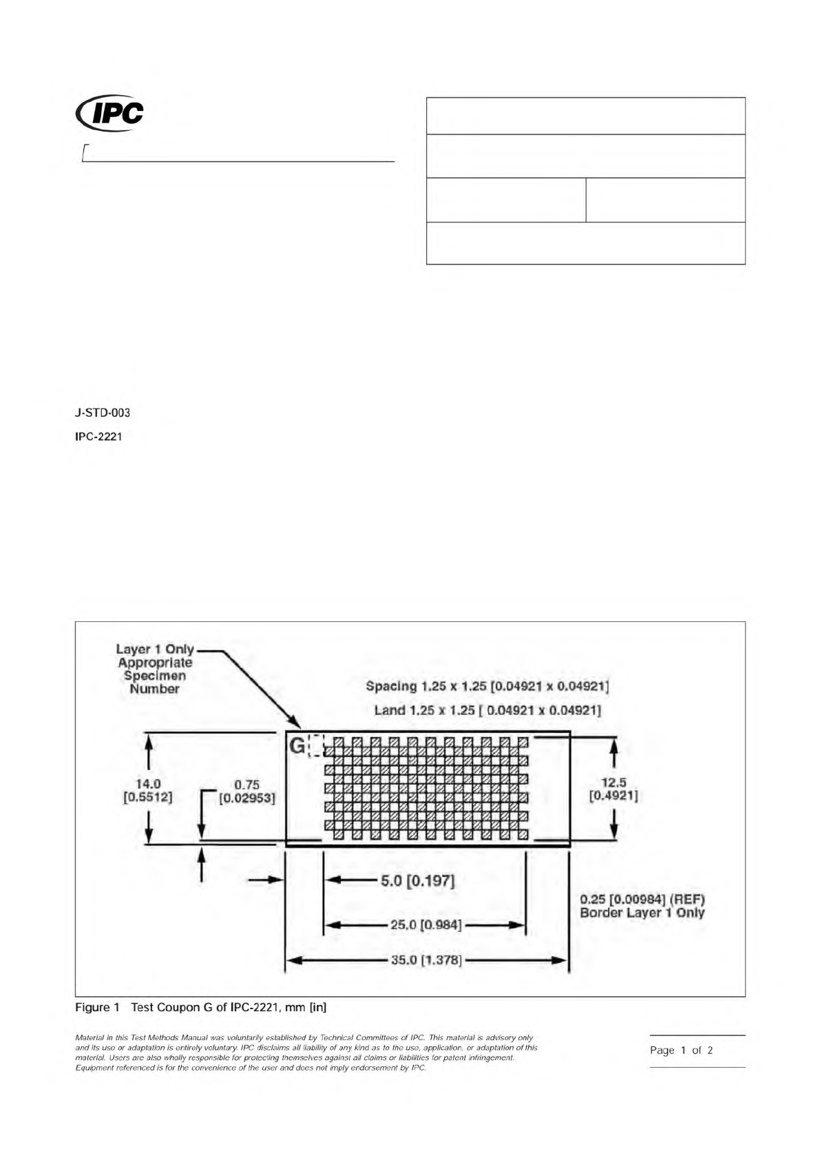
12.5
[0.4921]
0.25
[0.00984]
(REF)
Border
Layer
1
Only
—
0.75
|
[0.02953]
Spacing
1.25
X
1.25
[0.04921
x
0.04921]
Land
1.25
X
1.25
[
0.04921
X
0.04921]
Layer
1
Only
Appropriate
Specimen
Number
5.0
[0.197]
25.0
[0.984]
35.0
[1.378]
J-STD-003
IPC-2221
Figure
1
Test
Coupon
G
of
IPC-2221,
mm
[in]
Material
/n
this
Test
Methods
Manual
was
voluntarily
established
by
Technical
Committees
of
IPC.
This
material
,
s
advisory
only
and
"s
use
or
adaptation
,
s
entirely
voluntary.
IPC
disclaims
all
liability
of
any
kind
as
to
the
use,
application,
or
adaptation
of
this
material.
Users
are
also
wholly
responsible
for
protecting
themselves
against
all
claims
or
liabilities
for
patent
infringement.
Equipment
referenced
is
for
the
convenience
of
the
user
and
does
not
imply
endorsement
by
IPC.
Page
1
of
2
5.1.2
For preproduction qualification, test specimens are to
be cleaned using cleaning methods as recommended by the
solder resist manufacturer and standard production methods
for comparison purposes prior to solder resist application.
5.1.3
Test specimens are to be coated and cured by the
standard production method.
5.1.4
Testing is to be conducted on specimens before and
after soldering in accordance with J-STD-003, Methods A, B,
C, or D with no accelerated aging.
5.2 Test
5.2.1
Press a strip of pressure sensitive tape, 50 mm
[1.97 in] minimum in length, firmly across the surface of the
test area removing all air entrapment. The time between appli-
cation and removal of tape shall be less than one minute.
Remove the tape by a rapid pull force applied approximately
perpendicular (right angle) to the test area. An unused strip of
tape must be used for each test.
5.3 Evaluation
5.3.1
Visually examine the tape and test area for evidence of
any portion of the material tested having been removed from
the specimen.
5.3.2
The report should note any evidence of material
removed by this test.
6 Notes
6.1
Figure 1 illustrates the coupon that is used for testing.
The black squares indicate metal. The white squares indicate
the base material. Solder mask is applied over the entire con-
ductor pattern.
6.2
If foreign material (oil, grease, etc.) is present on the test
surface the results may be affected.
6.3
Certification of 3M Brand 600 1/2 inch tape to CID-A-A-
113 is not required. The 3M Brand 600 1/2 inch tape is avail-
able through most office supply stores.
Number
2.4.28.1
Subject
Solder Mask Adhesion - Tape Test Method
Date
03/07
Revision
F
IPC-TM-650
Page
2
of
2
1 Scope
This test method is used to determine the adhe-
sion quality of solder masks used on flexible circuits.
2 Applicable Documents
Double-Sided Artwork
3 Test Specimen
The IPC-A-42-G-KIT artwork package
provides the electronic Gerber information necessary for the
fabrication of the IPC B-42 test board. IPC-B-42 flexible test
patterns H1, H2, and/or H3, or production test samples with
solder mask coating. Each flexible section shall be separated
and tested independently.
4 Apparatus
3.18 ± 0.1 mm [0.125 ± 0.004 in] diameter
mandrel (metal rod).
5 Procedures
5.1 Test
5.1.1
Bend the test specimen around the mandrel so that
the ends of the test specimens are on the same side of the
mandrel and nominally parallel to each other. (The test speci-
men forms a ‘‘U’’ shape around the mandrel.) Each cycle
must be at the same point on the flexible circuit.
5.1.2
Flip the test specimen so that its opposite surface is
against the metal rod and repeat 5.1.1.
5.1.3
Repeat 5.1.1 and 5.1.2 nine times (ten cycles total) for
each of the test specimens.
5.2 Evaluation
Visually examine the flexible circuit test pat-
tern with corrected 20/20 vision without magnification for sol-
der mask delamination or cracks.
1. www.ipc.org/onlinestore
3000 Lakeside Drive, Suite 309S
Bannockburn, IL 60015-1249
IPC-TM-650
TEST METHODS MANUAL
Number
2.4.29
Subject
Solder Mask - Adhesion to Flexible Circuits
Date
03/07
Revision
C
Originating Task Group
Solder Mask Performance Task Group (5-33b)
ASSOCIATION CONNECTING
ELECTRONICS INDUSTRIES
®
IPC-A-42-G-KIT1
Material
/n
this
Test
Methods
Manual
was
voluntarily
established
by
Technical
Committees
of
I
PC.
This
material
/s
advisory
only
and
"s
use
or
adaptation
,
s
entirely
voluntary.
IPC
disclaims
all
liability
of
any
kind
as
to
the
use,
application,
or
adaptation
of
this
material.
Users
are
also
wholly
responsible
for
protecting
themselves
against
all
claims
or
liabilities
for
patent
infringement.
Equipment
referenced
/s
for
the
convenience
of
the
user
and
does
not
imply
endorsement
by
IPC.
Page
1
of
1