IPC-TM-650 EN 2022 试验方法--.pdf - 第183页
NOTE: NOTE: IPC-TM-650 Page 3 of 4 Number 2.3.25.1 Revision Subject Ionic Cleanliness Testing of Bare PWBs Date October 2000 Between measurements, rinse the cell with deionized water and leave the cell soaking in virgin …
NOTE:
NOTE:
NOTE:
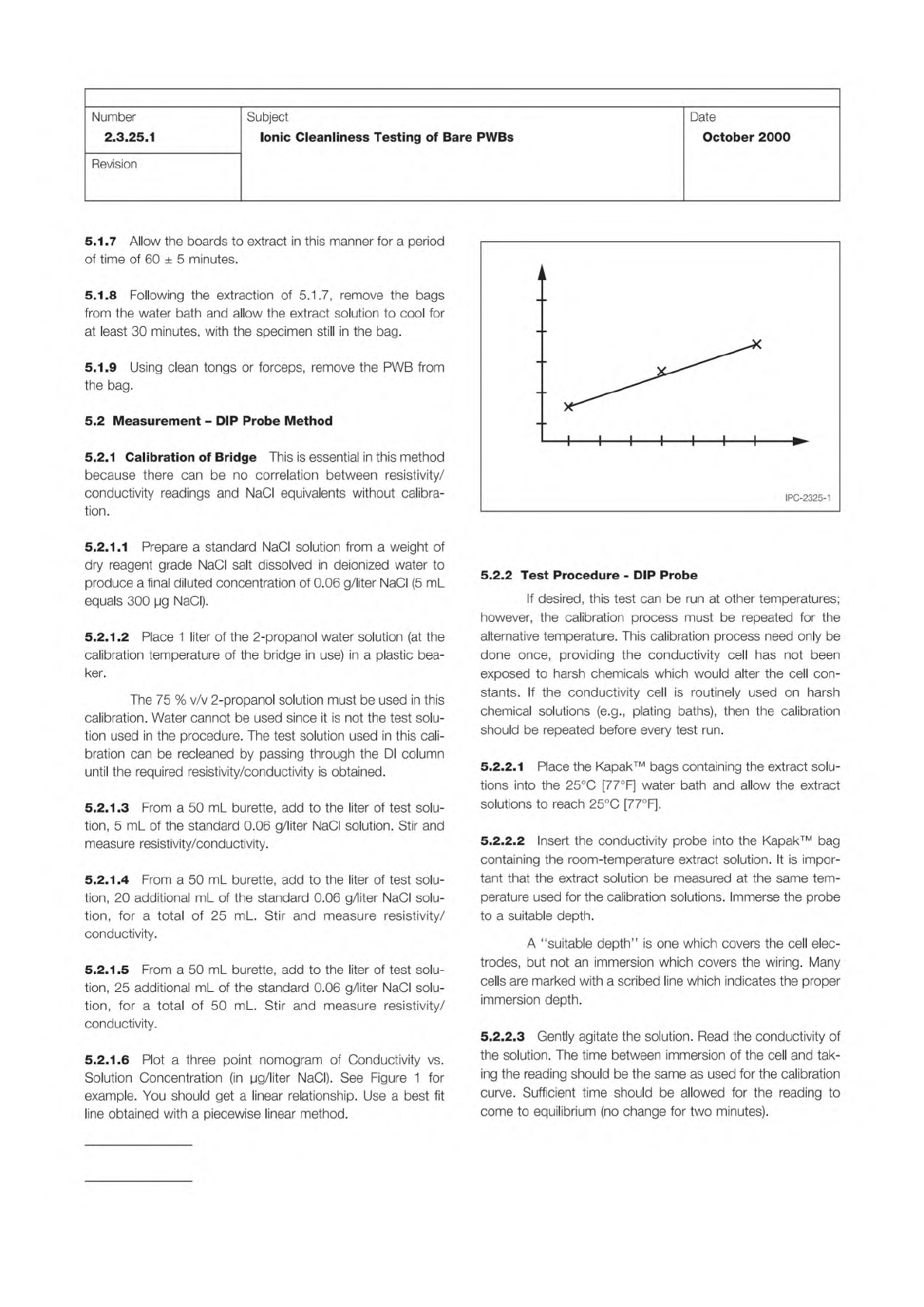
Figure 1 Nomogram of Conductivity vs. Solution
Concentration
Conductivity
Solution Concentr
ation
in micrograms NaCl/Liter
IPC-TM-650
Page 2 of 4
Number
2.3.25.1
Revision
Subject
Ionic
Cleanliness
Testing
of
Bare
PWBs
Date
October
2000
5.1.7
Allow
the
boards
to
extract
in
this
manner
for
a
period
of
time
of
60
±
5
minutes.
5.1.8
Following
the
extraction
of
5.1
.7,
remove
the
bags
from
the
water
bath
and
allow
the
extract
solution
to
cool
for
at
least
30
minutes,
with
the
specimen
still
in
the
bag.
5.1.9
Using
clean
tongs
or
forceps,
remove
the
PWB
from
the
bag.
5.2
Measurement
-
DIP
Probe
Method
5.2.1
Calibration
of
Bridge
This
is
essential
in
this
method
because
there
can
be
no
correlation
between
resistivity/
conductivity
readings
and
NaCI
equivalents
without
calibra¬
tion.
5.2.1.
1
Prepare
a
standard
NaCI
solution
from
a
weight
of
dry
reagent
grade
NaCI
salt
dissolved
in
deionized
water
to
produce
a
final
diluted
concentration
of
0.06
g/liter
NaCI
(5
mL
equals
300
pg
NaCI).
5.2.
1.2
Place
1
liter
of
the
2-propanol
water
solution
(at
the
calibration
temperature
of
the
bridge
in
use)
in
a
plastic
bea¬
ker.
The
75
%
v/v
2-propanol
solution
must
be
used
in
this
calibration.
Water
cannot
be
used
since
it
is
not
the
test
solu¬
tion
used
in
the
procedure.
The
test
solution
used
in
this
cali¬
bration
can
be
recleaned
by
passing
through
the
DI
column
until
the
required
resistivity/conductivity
is
obtained.
5.2.
1.3
From
a
50
mL
burette,
add
to
the
liter
of
test
solu¬
tion,
5
mL
of
the
standard
0.06
g/liter
NaCI
solution.
Stir
and
measure
resistivity/conductivity.
5.2.
1.4
From
a
50
mL
burette,
add
to
the
liter
of
test
solu¬
tion,
20
additional
mL
of
the
standard
0.06
g/liter
NaCI
solu¬
tion,
for
a
total
of
25
mL.
Stir
and
measure
resistivity/
conductivity.
5.2.
1.5
From
a
50
mL
burette,
add
to
the
liter
of
test
solu¬
tion,
25
additional
mL
of
the
standard
0.06
g/liter
NaCI
solu¬
tion,
for
a
total
of
50
mL
Stir
and
measure
resistivity/
conductivity.
5.2.1.
6
Plot
a
three
point
nomogram
of
Conductivity
vs.
Solution
Concentration
(in
pg/liter
NaCI).
See
Figure
1
for
example.
You
should
get
a
linear
relationship.
Use
a
best
fit
line
obtained
with
a
piecewise
linear
method.
5.2.2
Test
Procedure
-
DIP
Probe
If
desired,
this
test
can
be
run
at
other
temperatures;
however,
the
calibration
process
must
be
repeated
for
the
alternative
temperature.
This
calibration
process
need
only
be
done
once,
providing
the
conductivity
cell
has
not
been
exposed
to
harsh
chemicals
which
would
alter
the
cell
con¬
stants.
If
the
conductivity
cell
is
routinely
used
on
harsh
chemical
solutions
(e.g.,
plating
baths),
then
the
calibration
should
be
repeated
before
every
test
run.
5.2.2.1
Place
the
Kapak™
bags
containing
the
extract
solu¬
tions
into
the
25℃
[77°
F]
water
bath
and
allow
the
extract
solutions
t
。
reach
25℃
[77°F].
S.2.2.2
Insert
the
conductivity
probe
into
the
Kapak™
bag
containing
the
room-temperature
extract
solution.
It
is
impor¬
tant
that
the
extract
solution
be
measured
at
the
same
tem¬
perature
used
for
the
calibration
solutions.
Immerse
the
probe
to
a
suitable
depth.
A
"suitable
depth”
is
one
which
covers
the
cell
elec¬
trodes,
but
not
an
immersion
which
covers
the
wiring.
Many
cells
are
marked
with
a
scribed
line
which
indicates
the
proper
immersion
depth.
S.2.2.3
Gently
agitate
the
solution.
Read
the
conductivity
of
the
solution.
The
time
between
immersion
of
the
cell
and
tak¬
ing
the
reading
should
be
the
same
as
used
for
the
calibration
curve.
Sufficient
time
should
be
allowed
for
the
reading
to
come
to
equilibrium
(no
change
for
two
minutes).
NOTE:
NOTE:
IPC-TM-650
Page 3 of 4
Number
2.3.25.1
Revision
Subject
Ionic
Cleanliness
Testing
of
Bare
PWBs
Date
October
2000
Between
measurements,
rinse
the
cell
with
deionized
water
and
leave
the
cell
soaking
in
virgin
extract
solution.
Never
use
a
dry
cell
as
this
is
bad
technique.
5.2.2.4
Using
the
linear
relationship
formed
in
5.2.1
.6,
determine
the
concentration
of
sodium
chloride
correspond¬
ing
to
the
conductivity
reading.
Use
the
equation
given
below
to
determine
the
total
micrograms
of
sodium
chloride
equiva¬
lence
per
square
centimeter
(pg
NaCI
Eq.
/cm2)
Using
the
nomogram:
Conductivity
of
Unknown
一
Concentration
of
Unknown
Concentration
Volume
of
Extract
Solution
(pg/liter)
x
(liter)
Extracted
Surface
Area
(cm2)
二
pg
NaCI
Eq.
/cm2
5.2.2.5
If
the
conductivity
of
the
unknown
solution
is
outside
of
the
bounds
represented
on
the
existing
nomogram,
then
continue
the
technique
used
to
generate
the
nomogram
(see
5.2.1)
until
the
bounds
contain
the
conductivity
of
the
unknown
solution.
5.3
Measurement
-
Static
ROSE
Tester
Method
This
section
was
developed
using
an
Omegameter
600SMD
with
a
1
0,000
mL
cell.
Make
appropriate
changes
to
the
procedure
to
accommodate
other
static
ROSE
testers.
5.3.1
Perform
a
system
verification
check.
5.3.2
Set
the
instrument
to
an
appropriate
amount
of
sol¬
vent
volume.
A
target
solution
level
should
be
1.5
mL
for
one
cm2
of
board
surface.
It
is
not
necessary
to
cover
the
spray
jets
(if
applicable).
If
the
lid
is
on
the
test
cell,
the
C02
mixing
is
minimized.
5.3.3
Enter
the
appropriate
surface
area
into
the
instrument.
5.3.4
To
allow
for
the
volume
of
solvent
that
is
to
be
added,
the
instrument
setup
volume
will
be
set
at
the
minimum
vol¬
ume
(e.g.,
2300
mL)
plus
the
volume
of
solution
in
the
extrac¬
tion
bag
(e.g.,
100
mL).
Dwell
time
or
run
time:
2
minutes
Pass
/
Fail
Value:
None
Begin
the
test
and
follow
the
test
prompts.
Remove
the
cell
cover.
5.3.5
Carefully
open
the
test
bag
and
quickly
pour
the
extract
solution
into
the
test
cell.
To
minimize
CO2
absorption,
the
addition
should
be
made
as
quickly
as
possible
and
the
cell
cover
quickly
replaced.
5.3.6
The
instrument
should
very
quickly
reach
equilibrium
(10-15
seconds)
and
then
should
remain
essentially
unchanged
for
the
remainder
of
the
two
minute
run.
5.3.7
Log
the
reading
in
total
pg
of
sodium
chloride
equiva¬
lence
per
cm2.
5.3.8
Static
ROSE
Calculation
Example:
Testing
a
bare
board,
10
cm
x
20
cm
[3.9
in
x
7.9
in]
Surface
area
is
1
0
cm
x
20
cm
x
2
=
400
cm2
[62
in2]
Bag
size
should
be
about
1
5
cm
x
30
cm
[5.9
in
x
12
in]
or
larger
Extract
solution
would
be
about
620
mL
ROSE
volume
input
to
4620
mL
(4000
mL
to
cover
sprays
and
620
mL
from
extraction)
ROSE
tester
cell
volume
set
to
4000
mL
Run
time
-
2
minutes
5.4
Measurement
-
Dynamic
ROSE
Tester
Method
5.4.1
Perform
a
system
verification
check.
5.4.2
Program
the
instrument
with
the
appropriate
surface
area
of
the
board.
5.4.3
Cycle
the
instrument
to
the
beginning
cleanliness
point.
5.4.4
Carefully
open
the
test
bag
and
quickly
pour
the
extract
solution
into
the
test
cell.
To
minimize
CO2
absorption,
the
addition
should
be
made
as
quickly
as
possible
and
the
cell
cover
quickly
replaced.
5.4.5
When
the
instrument
completes
the
test,
log
the
read¬
ing
in
total
pg
of
sodium
chloride
equivalence
per
cm2.
6
Notes
6.1
The
background
for
this
test
method
may
be
found
in
technical
papers:
11
Rationale
and
Methodology
for
a
Modified
Resistivity
of
Sol¬
vent
Extract
Test
Method/'
Philip
W.
Wittmer,
I
PC
1995
Fall
Meeting
Proceedings,
S13-4.
IPC-TM-650
Page 4 of 4
Number
2.3.25.1
Subject
Ionic
Cleanliness
Testing
of
Bare
PWBs
Date
October
2000
Revision
“Ionic
Cleanliness
of
LPISM
Circuit
Boards,"
Hank
Sanftle-
ben,
IPO
1995
Fall
Meeting
Proceedings,
S13-3.
6.2
IPC-HDBK-001
"Handbook
and
Guide
to
the
Require¬
ments
for
Soldered
Electrical
and
Electronic
Assemblies
to
Supplement
ANSI/J-STD-001
"
is
another
source
for
under¬
standing
ROSE
testing
in
general.
6.3
This
method
may
also
be
known
as
the
modified-ROSE
test.
This
test,
due
to
its
longer
extraction
time
and
higher
extraction
temperature,
has
demonstrated
better
correlation
with
the
total
ion
determination
by
ion
chromatography
than
IPC-TM-650,
Test
Method
2.3.25,
Detection
and
Measure¬
ment
of
Ionizable
Surface
Contaminants
by
Resistivity
of
Sol¬
vent
Extract
(ROSE)
Method.
However,
as
a
bulk
contamina¬
tion
measurement
method,
it
cannot
distinguish
individual
ion
species.
6.4
From
an
analytical
standpoint,
the
dip
probe
method
is
preferred
as
more
repeatable
than
the
automated
ROSE
testers
and
avoids
many
of
the
test
inaccuracies
(e.g.,
C02
absorption
from
spray
agitation)
inherent
in
those
instruments.
It
should
be
stressed
that
the
dip
probe
method
is
an
electro¬
lytic
conductivity
measurement
and
must
be
temperature-
compensated.
6.5
The
dip
probe
calibrations
can
be
run
at
multiple
tem¬
peratures
and
a
family
of
curves
generated,
widening
the
test
window
for
use
with
this
method.
Higher
temperatures,
how¬
ever,
will
lead
to
a
faster
2-propanol
evaporation
rate.
The
test
can
also
be
run
with
more
dilute
concentrations,
prepared
by
series
dilution.
6.6
Conductivity
cells
have
a
“constant”
value.
Measured
readings
must
be
multiplied
by
this
constant.
Exposure
to
harsh
chemicals
may
alter
the
constant,
making
a
re-calibration
necessary.
Do
not
allow
the
probe
used
for
this
procedure
to
contact
sticky,
oily,
or
resinous
liquids
(e.g.,
flux).
6.7
This
procedure
is
intended
to
be
a
process
control
aid
and
as
such,
no
pass-fail
criteria
is
stated.
It
is
expected
that
the
fabricator/assembler
will
determine,
with
their
customer,
the
necessary
pass-fail
criteria
for
their
product
by
this
method.
6.8
This
method
is
best
suited
for
monitoring
and
control
of
a
previously
optimized
process
and
should
not
be
used
to
generate
acceptance
data
unless
part
of
a
larger
correlation
study.
Values
generated
with
this
method
should
be
corre¬
lated
to
acceptable
electrical
performance
if
used
for
accep¬
tance.
6.9
Kapak™
500
Series
Bags
can
be
obtained
from:
Kapak
Corporation
5305
Parkdale
Drive
Minneapolis,
MN
55416
800-527-2557
www.kapak.com
A
secondary
source
of
Kapak™
or
Scotchpak™
polyester
bags
or
pouches
can
be
obtained
from:
VWR
International
1310
Goshen
Parkway
West
Chester,
PA
1
9380
Orders:
1-800-932-5000
Web
Orders:
www.vwrsp.com
If
an
alternative
to
the
Kapak™
bag
or
Scotchpak™
is
desired,
the
bag
must
have
the
following
characteristics:
•
No
extractable
ionic
material
in
75%
2-propanol
/
25%
DI
water
at
80℃
[1
76°F]
for
60
minutes
•
0.01
cm
[0.0039
in]
wall
thickness
minimum
•
Heat
sealable
or
mechanical
seal
6.10
There
is
some
concern
regarding
ROSE
tester
cell
size.
Testing
a
2
cm
x
2
cm
[0.79
in
x
0.79
in]
board
in
a
20,000
mL
cell
causes
such
a
severe
dilution
as
to
cause
the
signal
to
be
lost
in
the
noise.
A
recommended
cell
size
is
5000
mL
or
less.
Smaller
cell
volumes
will
allow
for
a
more
measurable
result.
If
a
smaller
cell,
or
running
with
a
smaller
test
volume,
are
not
an
option,
then
the
number
of
bare
boards
can
be
increased,
all
extracted
separately,
and
the
extract
solutions
all
tested
at
once.
6.1
1
When
testing
hybrids
or
microelectronics,
be
aware
that
2-propanol
stored
in
glass
containers
can
leach
out
materials
such
as
sodium,
borates,
and
silica.
2-propanol
stored
in
plastic
containers
does
not
have
such
a
leaching
problem.