IPC-TM-650 EN 2022 试验方法--.pdf - 第155页
Figure 1 Porosity T est Schematic mA VM P ower Supply o-1 a DC o-10 V - + - + T eflon® Gold Clad Plate Photographic Pa per , Silver Halide Free Sample Under T est T ef lon® IPC-TM-650 Number Subject Date Revision Page 3 …
/
/
IPC-TM-650
Number
Subject Date
Revision
Page 2 of 3
2.3.24.1
Porosity
Testing
of
Gold
Electrodeposited
on
a
Nickel
Plated
Copper
Substrate
Electrographic
Method
10/85
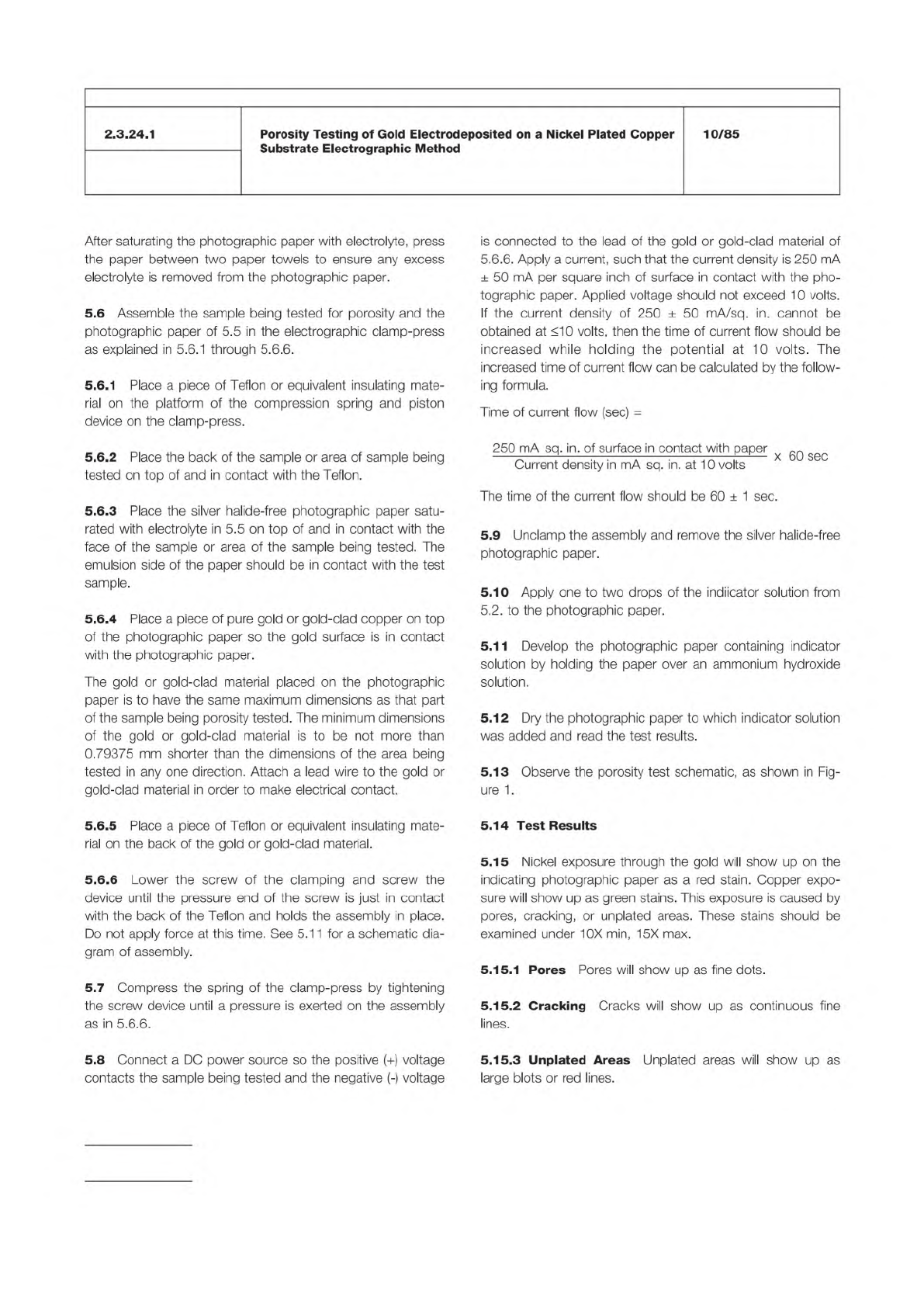
After
saturating
the
photographic
paper
with
electrolyte,
press
the
paper
between
two
paper
towels
to
ensure
any
excess
electrolyte
is
removed
from
the
photographic
paper.
5.6
Assemble
the
sample
being
tested
for
porosity
and
the
photographic
paper
of
5.5
in
the
electrographic
clamp-press
as
explained
in
5.6.1
through
5.6.6.
5.6.1
Place
a
piece
of
Teflon
or
equivalent
insulating
mate¬
rial
on
the
platform
of
the
compression
spring
and
piston
device
on
the
clamp-press.
5.6.2
Place
the
back
of
the
sample
or
area
of
sample
being
tested
on
top
of
and
in
contact
with
the
Teflon.
5.6.3
Place
the
silver
halide-free
photographic
paper
satu¬
rated
with
electrolyte
in
5.5
on
top
of
and
in
contact
with
the
face
of
the
sample
or
area
of
the
sample
being
tested.
The
emulsion
side
of
the
paper
should
be
in
contact
with
the
test
sample.
5.6.4
Place
a
piece
of
pure
gold
or
gold-clad
copper
on
top
of
the
photographic
paper
so
the
gold
surface
is
in
contact
with
the
photographic
paper.
The
gold
or
gold-clad
material
placed
on
the
photographic
paper
is
to
have
the
same
maximum
dimensions
as
that
part
of
the
sample
being
porosity
tested.
The
minimum
dimensions
of
the
gold
or
gold-clad
material
is
to
be
not
more
than
0.79375
mm
shorter
than
the
dimensions
of
the
area
being
tested
in
any
one
direction.
Attach
a
lead
wire
to
the
gold
or
gold-clad
material
in
order
to
make
electrical
contact.
5.6.5
Place
a
piece
of
Teflon
or
equivalent
insulating
mate¬
rial
on
the
back
of
the
gold
or
gold-clad
material.
5.6.6
Lower
the
screw
of
the
clamping
and
screw
the
device
until
the
pressure
end
of
the
screw
is
just
in
contact
with
the
back
of
the
Teflon
and
holds
the
assembly
in
place.
Do
not
apply
force
at
this
time.
See
5.1
1
for
a
schematic
dia¬
gram
of
assembly.
5.7
Compress
the
spring
of
the
clamp-press
by
tightening
the
screw
device
until
a
pressure
is
exerted
on
the
assembly
as
in
5.6.6.
5.8
Connect
a
DC
power
source
so
the
positive
(+)
voltage
contacts
the
sample
being
tested
and
the
negative
(-)
voltage
is
connected
to
the
lead
of
the
gold
or
gold-clad
material
of
5.6.6.
Apply
a
current,
such
that
the
current
density
is
250
mA
±
50
mA
per
square
inch
of
surface
in
contact
with
the
pho¬
tographic
paper.
Applied
voltage
should
not
exceed
1
0
volts.
If
the
current
density
of
250
±
50
mA/sq.
in.
cannot
be
obtained
at
≤1
0
volts,
then
the
time
of
current
flow
should
be
increased
while
holding
the
potential
at
1
0
volts.
The
increased
time
of
current
flow
can
be
calculated
by
the
follow¬
ing
formula.
Time
of
current
flow
(sec)
=
250
mA
sq.
in.
of
surface
in
contact
with
paper
心八
Current
density
in
mA
sq.
in.
at
1
0
volts
The
time
of
the
current
flow
should
be
60
±
1
sec.
5.9
Unclamp
the
assembly
and
remove
the
silver
halide-free
photographic
paper.
5.10
Apply
one
to
two
drops
of
the
indiicator
solution
from
52
to
the
photographic
paper.
5.1
1
Develop
the
photographic
paper
containing
indicator
solution
by
holding
the
paper
over
an
ammonium
hydroxide
solution.
5.12
Dry
the
photographic
paper
to
which
indicator
solution
was
added
and
read
the
test
results.
5.13
Observe
the
porosity
test
schematic,
as
shown
in
Fig¬
ure
1
.
5.14
Test
Results
5.15
Nickel
exposure
through
the
gold
will
show
up
on
the
indicating
photographic
paper
as
a
red
stain.
Copper
expo¬
sure
will
show
up
as
green
stains.
This
exposure
is
caused
by
pores,
cracking,
or
unplated
areas.
These
stains
should
be
examined
under
10X
min,
15X
max.
5.15.1
Pores
Pores
will
show
up
as
fine
dots.
5.15.2
Cracking
Cracks
will
show
up
as
continuous
fine
lines.
5.15.3
Unplated
Areas
Unplated
areas
will
show
up
as
large
blots
or
red
lines.
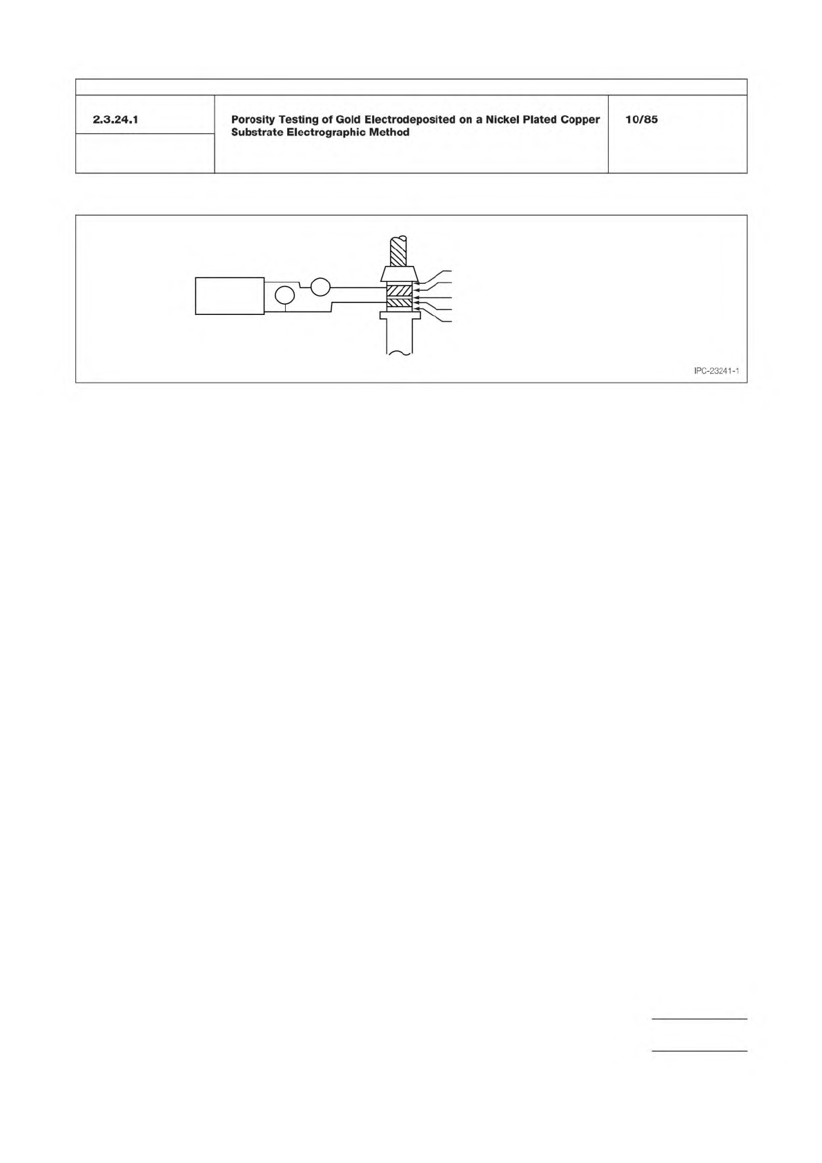
Figure 1 Porosity Test Schematic
mA
VM
Power Supply
o-1 a DC
o-10 V
-
+
-
+
Teflon®
Gold Clad Plate
Photographic Paper, Silver Halide Free
Sample Under Test
Teflon®
IPC-TM-650
Number
Subject Date
Revision
Page 3 of 3
Porosity
Testing
of
Gold
Electrodeposited
on
a
Nickel
Plated
Copper
Substrate
Electrographic
Method
10/85
2.3.24.1
IPC-23241-1
Caution: No sealant (e.g., stopcock grease, etc.) shall be
applied to the mating surfaces of the desiccator cover or
bottom. Sealants may cause these to stick together, and any
method employed to release a stuck cover is likely to be
extremely hazardous.
Caution: Perform all work in hood, since the vapors given off
are toxic. Chemical goggles, completely closing the eyes,
should be worn and eyewash facilities should be readily
available.
Material in this Test Methods Manual was voluntarily established by Technical Committees of the IPC. This material is advisory only
and its use or adaptation is entirely voluntary. IPC disclaims all liability of any kind as to the use, application, or adaptation of this
material. Users are also wholly responsible for protecting themselves against all claims or liabilities for patent infringement.
Equipment referenced is for the convenience of the user and does not imply endorsement by the IPC.
Page 1 of 2
r
ASSOCIATION
CONNECTING
/
ELECTRONICS
INDUSTRIES
221
5
Sanders
Road
Northbrook,
IL
60062-6135
IPC-TM-650
TEST
METHODS
MANUAL
1.0
Outline
for
Methods
The
part
is
exposed
to
an
atmo¬
sphere
that
is
corrosive
to
the
basis
metal.
Where
there
is
porosity,
the
reagent
attacks
the
basis
metal
and
generates
corrosion
products.
The
part
is
examined
for
corrosion
prod¬
ucts.
1.1
Method
1
(Nitric
Acid
Vapor-Gold
on
Copper)
This
method
applies
only
to
gold
coatings
on
copper
and
copper-
base
alloys.
1
.2
Method
2
(Extended
Nitric
Acid
Vapor)
This
method
applies
only
to
gold
coatings
on
copper
and
copper-base
alloys.
1.3
Method
3
(Nitric
Acid
Vapor
-
Gold
on
Nickel)
This
method
applies
to
gold
coatings
on
copper,
copper-base
alloys,
and
nickel.
2
.0
Nitric
Acid
Vapor
-
Gold
on
Copper
2.1
Apparatus
Methods
1
,
2,
and
3.
2.1.1
Collimated
Incandescent
Lamp
No.
31-33-53,
Bausch
and
Lomb
Co.,
or
No.
359,
American
Optical
Co.,
or
equivalent.
2.1.2
Desiccator
(Glass)
Fisher
Scientific
Co.
Series
8-595
or
8-624
or
equivalent.
The
size
of
the
desiccator
shall
be
chosen
so
that
no
more
than
1
64
cm3
of
air
space
exists
for
6.45
cm2
of
nitric
acid
surface
area
when
approximately
301
ml
of
acid
are
placed
in
the
bottom.
2.1.3
Part
Support
A
supporting
structure
made
of
glass
or
other
material
not
attached
by
nitric
acid
vapors
to
hold
the
parts
under
test
in
the
upper
part
of
the
desiccator.
2.1.4
Oven
An
oven
capable
of
drying
parts
at
125℃.
Number
2.3.24.2
Subject
Porosity
of
Metallic
Coatings
on
Copper-Base
Alloys
and
Nickel
(Nitric
Acid
Vapor
Test)
Date
Revision
8/97
A
Originating
Task
Group
N/A
2.1.5
Pressure
Sensitive
Polytetrafluoroethylene
Tape
with
Silicone
Adhesive
Backing
Connecticut
Hard
Rubber
Company
TFE
Type
HM225
or
equivalent.
2.2
Reagents
Methods
1
and
2.
Nitric
Acid,
69,
0
to
71.0
Percent
HN03.
3
.0
Procedure
3.1
Method
1
(Nitric
Acid
Vapor-Gold
on
Copper)
To
minimize
and
tendency
for
the
cover
to
stick,
press
a
mini¬
mum
of
three
strips
of
the
pressure
polytetrafluoroethylene
tape
(adhesive
side
down)
at
equal
intervals
around
the
mat¬
ting
surface
of
the
bottom
of
the
desiccator.
Place
approxi¬
mately
300
ml
of
nitric
acid
in
the
bottom
of
the
desiccator.
Cover
the
desiccator
and
allow
about
30
minutes
for
equilib¬
rium
to
be
established
before
starting
the
test.
This
equilibrium
is
necessary
only
when
the
nitric
acid
is
first
placed
in
the
desiccator.
Clean
the
part
with
1,1,1
-trichloroethane
or
toluene
or
other
suitable
solvent
and
dry
with
filtered
dry
air
(gage
pressure
less
than
207
kPa
(30
psi)).
Inspect
the
cleaned
part
at
10
power
magnification
for
evi¬
dence
or
particulate
matter
of
the
surface.
If
any
remains,
reclean
the
solvent
or
use
a
clean
soft
brush
to
remove
it
prior
to
the
start
of
the
porosity
test.
Place
the
clean
part
on
the
support
so
that
adequate
space
exists
to
allow
circulation
of
acid
vapor
and
air
around
it.
Carefully
remove
the
desiccator
cover,
place
the
support
in
the
desiccator
and
immediately
replace
the
cover
to
prevent
an
excessive
loss
of
vapors
that
would
disrupt
the
equilibrium
previously
established.
The
test
shall
be
performed
at
a
tem¬
perature
of
24
±
3
℃
and
a
maximum
relative
humidity
of
60
percent.
Unless
otherwise
specified,
the
time
of
exposure
to
the
reagent
vapor
shall
be
one
hour.